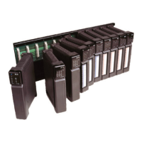
Kingfisher Plus+ Hardware Manual
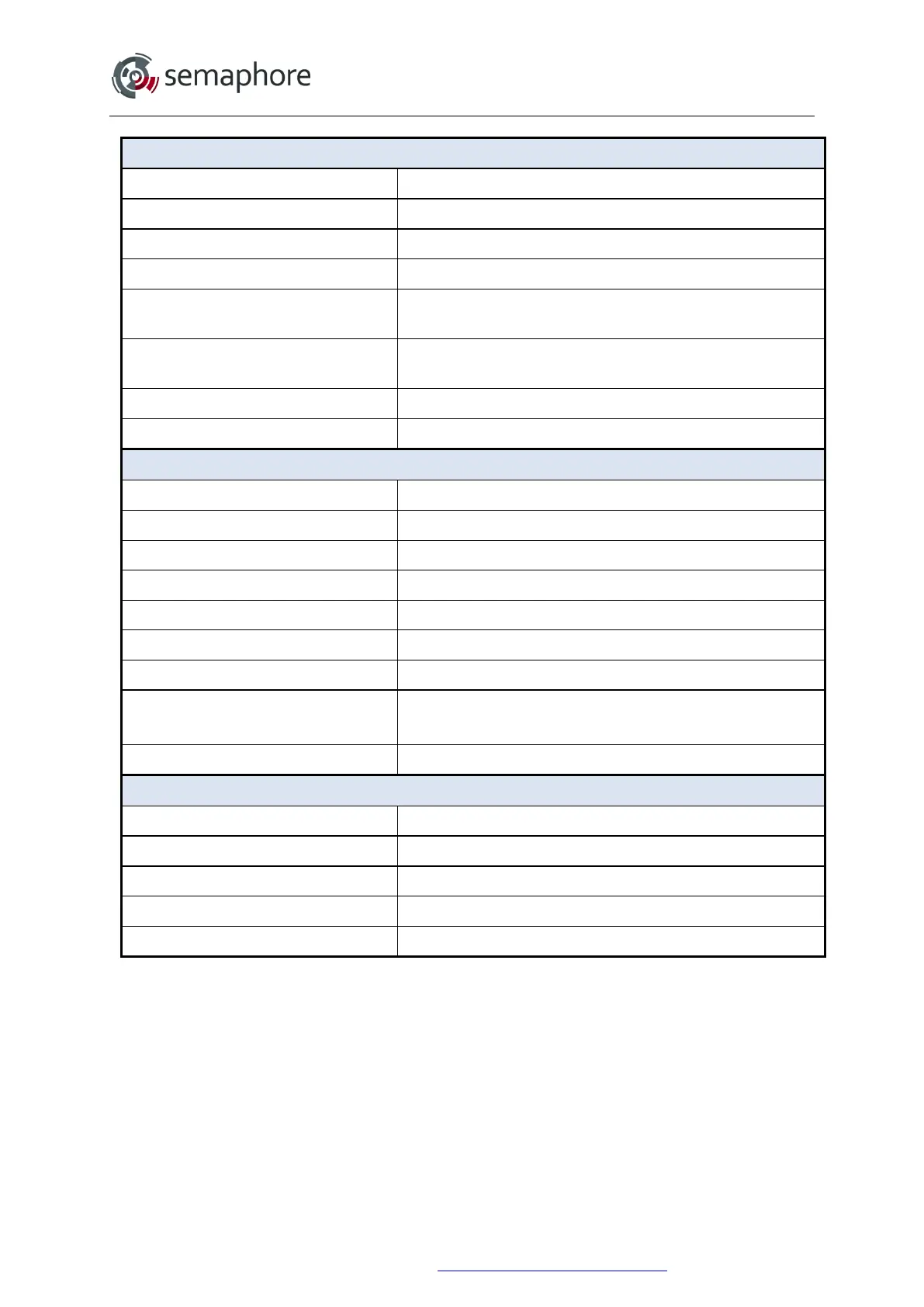
ANALOGUE OUTPUT
Output Current Range 4 - 20 mA or 0 - 20 mA
Outputs per Module 1
Output Type Isolated, Sourcing
Resolution Unsigned 12 bit
Update Rate
250 ms
Determined by I/O scan time and is application dependent
Accuracy (includes Gain,
Linearity and Offset errors)
± 0.25% @ 25°C
± 0.50% @ -40 to +85 °C
User Load 0 to 850 Ω
Isolation 5 kV Transient
DIGITAL INPUTS
Inputs per Module 4 with one common
Input Type Optically isolated, Sinking
Maximum Input Voltage 30 V
DC
Guaranteed ON-state Voltage 10 V
DC
minimum
Guaranteed OFF-state Voltage 4.0 V
DC
maximum
Counters Type Pulse, Unsigned 16-bit (all channels)
Maximum Counters Speed 10 kHz
Input Current
Approx. (V
IN
/ 4.7) mA:
2 mA @ 9.4 V
IN
; 6.4 mA @ 30 V
IN
Isolation 5 kV Transient
DIGITAL OUTPUTS
Outputs per Module 4 with one common
Output Type Optically isolated, Solid State, Sinking
Maximum Switched Voltage 30 V
DC
Maximum Switched Current 2 A per channel
Isolation 3 kV Transient
* Analogue inputs can be modified from current inputs to voltage inputs by lifting one pin (or
by the complete removal) of the 250 Ω channel resistor. Each channel has its own resistor,
so any combination of channels can be converted. It is recommended that modules be
returned to Semaphore for factory conversion if required. No responsibility will be taken by
Semaphore for damage caused to boards during modification performed by clients. The
circuit board resistors to change are:
• Ch.1: R81 (or R85+R86);
• Ch.2: R82 (or R87+R88);
• Ch.3: R83 (or R89+R90);
• Ch.4: R84 (or R91+R92).
Hardware Manual Version 7.16
http://www.servelec-semaphore.com/
Page 222