Kingfisher Plus+ Hardware Manual
Avertissement de Sécurité
Le terminal de terre à l’entrée de l’alimentation secteur est
uniquement une connexion de TERRE FONCTIONNELLE.
On ne peut pas compter sur lui pour assurer la sécurité.
The PS-x2/PS-x1 modules provide AC-DC (PS-12 and PS-11 only) or DC-DC conversion
from mains power into 12 V
DC
and 5 V
DC
for the backplane, as well as 12 V
DC
and optional
24 V
DC
auxiliary outputs. Both auxiliary outputs can be controlled by the RTU logic
configuration.
An isolated 24 V
DC
output rated at 6 W (250 mA) is an option available for powering a limited
number of analogue loops or digital circuits. It cannot be used with inductive loads such as
coils, contactors etc. Power for these is to be provided from a separate supply.
The PS-x2/PS-x1 is supplied with an internal temperature sensor to monitor its PCB
temperature and an optional external temperature sensor to monitor a backup battery. When
the battery is connected, the supplied external sensor should be mounted in the vicinity of
the battery negative terminal to ensure correct temperature compensation. If readings from
the external temperature sensor are out of range, internal sensor data is used. Boost charge
is disabled when external temperature sensor is faulty, not connected or if the battery
temperature is out of range. Please note the charge circuitry is designed for float operation
and short term boost of batteries already charged and in good condition. Use of this supply
on flat or fully discharged batteries may cause damage to the module.
The 12V Rail Voltage, Supply Current, Battery Current, internal and, optionally, external
temperature monitoring circuits, various status and controls registers enable the RTU to
monitor and to control all functions of the PS-x2/PS-x1 module. The Processor Module has
access to many of these values as analogue and digital points in the system.
If the Mains power interrupted and the system is powered from the backup battery, the
PS-x2/PS-x1 enters Low Battery Shutdown when battery voltage drops below 10.6 V. All
outputs are switched OFF for battery preservation, including Backplane power as well –
effectively meaning that the whole RTU will be shut down. PS-x2/PS-x1 switches itself to the
lowest power consumption mode possible, further preserving the battery from deep
discharge. PS-x2/PS-x1 checks rail voltage regularly, and the Backplane power will be
restored when +12V_RAIL voltage rises above 12.4 V (if no Mains present) or 11.2 V (if
Mains present).
Besides various hardware protection features, PS-x2/PS-x1 firmware provides additional
protection from overload. If output power exceeds its maximum specified power, the Switch-
mode Power Supply (SMPS) will enter an Overload Mode. Its output voltage will be ramped
down and, if overload still persists when it reaches 10.0 V (minimal output voltage), it will
switch all outputs off, similar to Low Battery Shutdown. PS-x2/PS-x1 will attempt to switch
the Backplane ON again regularly. RTU power will be restored permanently when overload
condition is removed.
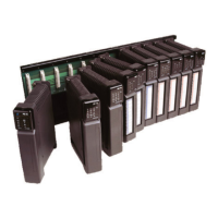
Several Power Supply modules of any type can be installed on a backplane thus providing
redundant and alternative power source configurations.
Hardware Manual Version 7.16
http://www.servelec-semaphore.com/
Page 37