Parameter Description
<Setting>
• When the operation frequency is smaller than P.2, the operation frequency will be equal to
the minimum limited frequency P.2. When the operation frequency is larger than P.1, the
operation frequency will be equal to the maximum limited frequency P.1
• After multiplying the setting frequency by the set value of P.185, then addition and
subtraction can be performed as following shows:
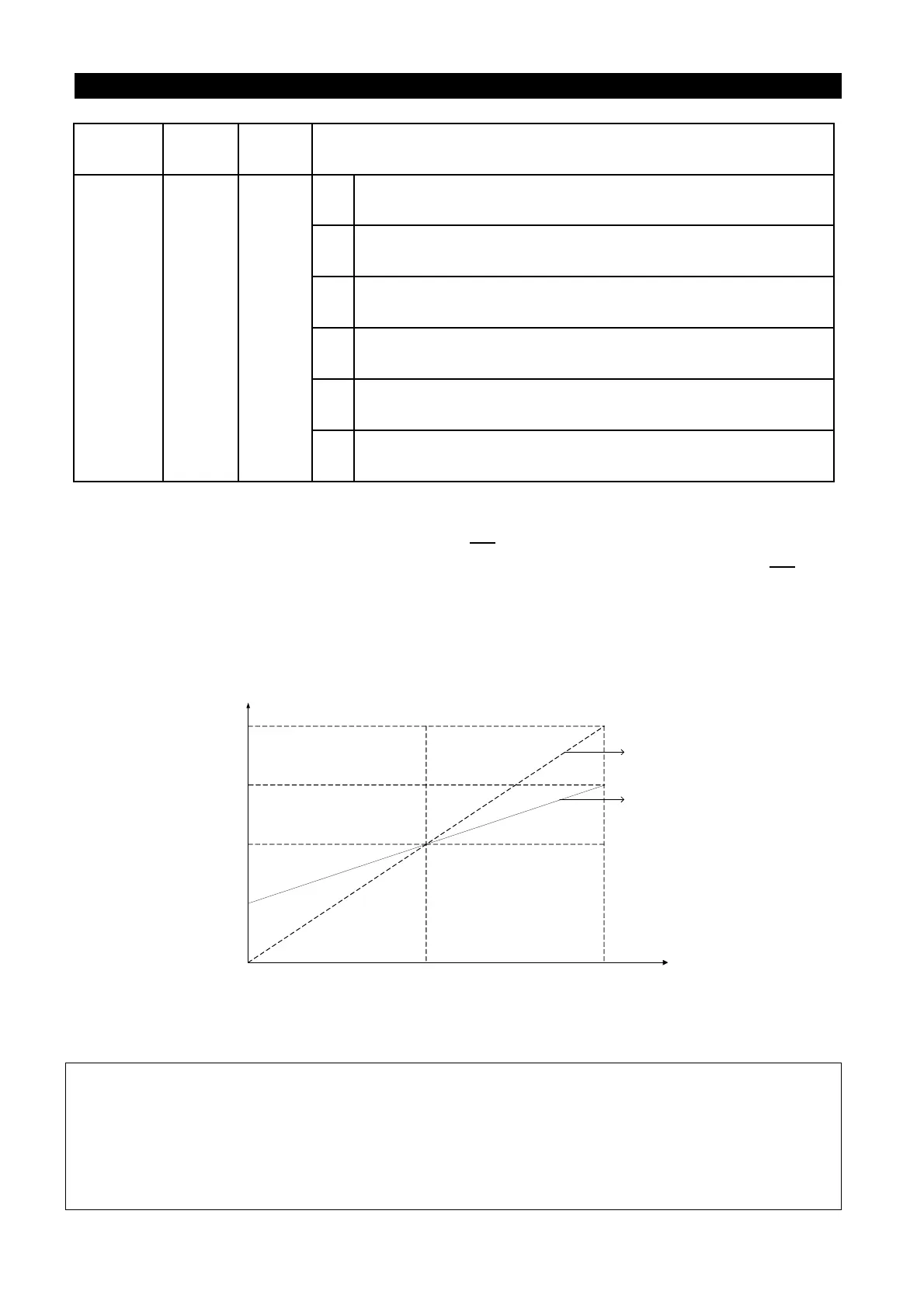
For example: When the setting frequency is 50Hz, P.185=50% and the external analog
input signal is 0~10V.
25HZ
0V 5V 10V
50HZ
75HZ
100HZ
The target frequency
Given by the voltage
of terminal 2-5
P.185=100%
P.185=50%
In the above figure, when 0V is given, the target frequency is 50Hz - (50Hz × 50%) = 25Hz;
When 5V is given, the target frequency is 50Hz - (50Hz × 0%) = 50Hz;
When 10V is given, the target frequency is 50Hz + (50Hz × 50%) = 75Hz.
Remarks
240 0 0~9
4
operation frequency = basic frequency - auxiliary
frequency (given by the 4-5 terminal)
5
operation frequency = given by the terminal 2-5 as the
proportion linkage signal
6
operation frequency = given by the terminal 4-5 as the
proportion linkage signal
7
operation frequency = given by the terminal 1-5 as the
proportion linkage signal
8
operation frequency = basic frequency + auxiliary
frequency (given by the terminal 1-5)
9
operation frequency = basic frequency - auxiliary
frequency (given by the terminal 1-5)
Note: 1. The basic frequency is set by DU01 which is the target frequency reference source,
communication or multi-speed combination.
2. Please refer to the instruction of P.240 for the proportion linkage signal input.
3. When the analog current/voltage signal of external terminal 4-5 is taken as the proportion linkage
input signal, please refer to the parameter P.17. For the frequency range setting of external
analog signal, please refer to the parameters P.38, P.39, P.509, P.17, P.73, P.530.

 Loading...

