Parameter Description
5.31 Zero Current Detection (P.62 and P.63)
P.62 “Zero current detection level”
P.63 “Zero current detection time”
Parameter Factory setting Setting range Remarks
62 5% 0~200%, 99999 Function invalid
63 0.5s 0.05~1s, 99999 Function invalid
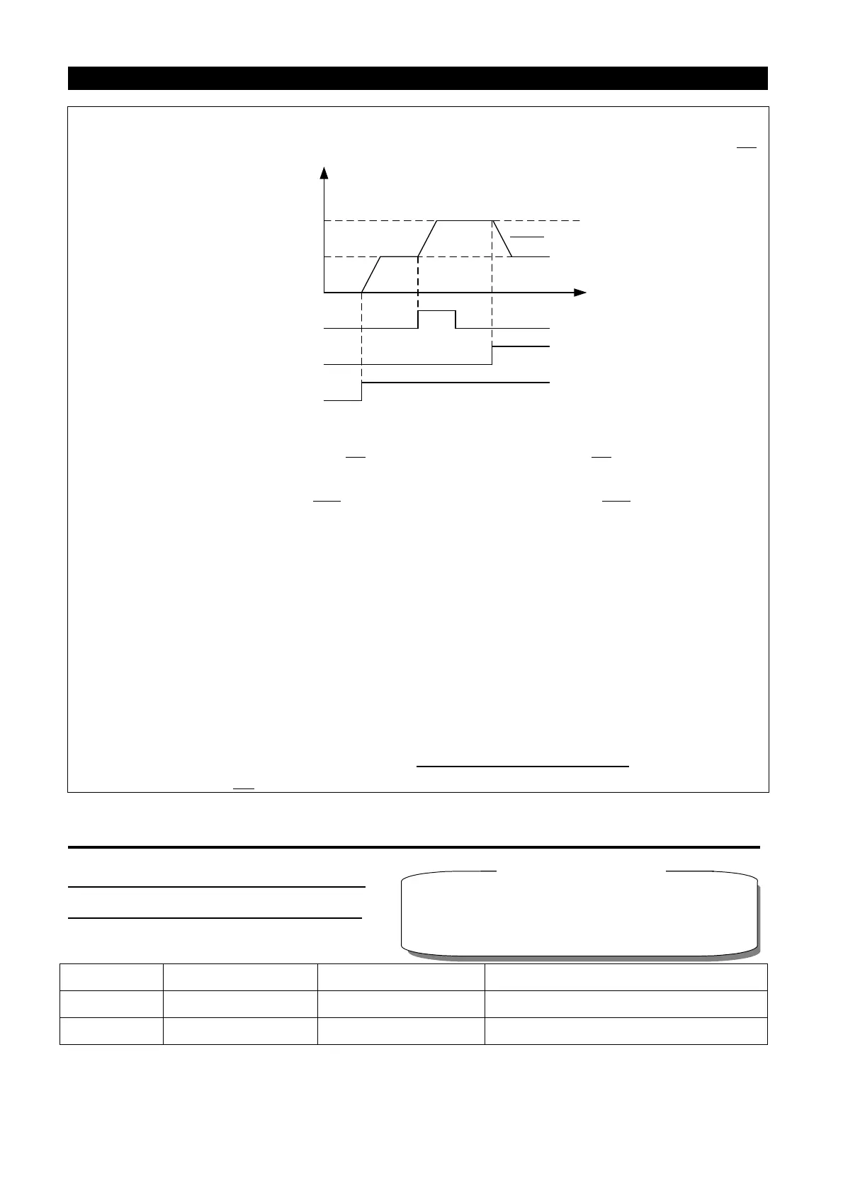
Note: 1. The frequency can be varied by RH (acceleration) and RM (deceleration) between 0 and (the
maximum frequency – frequency set by the main speed). The output frequency is limited by P.1
.
P.1
Output
frequency
Setting frequency
0Hz
Hz
Acceleration(RH)
Deceleration(RH)
Forward rotation
(STF)
ON
ON
ON
2. When the acceleration or deceleration signal is “on”, the acceleration / deceleration time will be
determined by the set value of P.7 (the first acceleration time) and P.8
(the first deceleration
time).
3. When RT signal is “on” and P.44≠99999 (the second acceleration time), P.45≠99999 (the second
deceleration time), the acceleration / deceleration time will be determined by the set value of P.44
and P.45.
4. When the start signal (STF/STR) is “off” and RH (acceleration) / RM (deceleration) is “on”, the
target frequency will also change.
5. When the start signal (STF/STR) becomes “off”, make the frequency setting storage function
invalid (P.61=2, 3) if the frequency has to be changed continuously through RH/RM.
frequency setting storage function is valid (P.61=1), the life of EEPROM will be shortened by
frequent EEPROM data writing.
6. RH, RM and RL mentioned in this chapter are function names of “multi-function control terminal”.
If the functions of the terminals are changed, other functions are likely to be affected. Please
verify the functions of the terminals before changing the options and functions of the
multi-function control panel (please refer to P.8 0~P.84、P.86、P.1 26、P.550
). For wiring, please
refer to Section 3.5.
Related parameters
P.40
“Muti-function output terminal SO1-SE function selection
”
P.
85
“
Function selection for multi-function relay A1-B1-C1
”
P.129
“
Function selection for multi-function output terminal SO2-SE”
P.130
“Function selection for multi-function relay A2-B2-C2"

 Loading...

