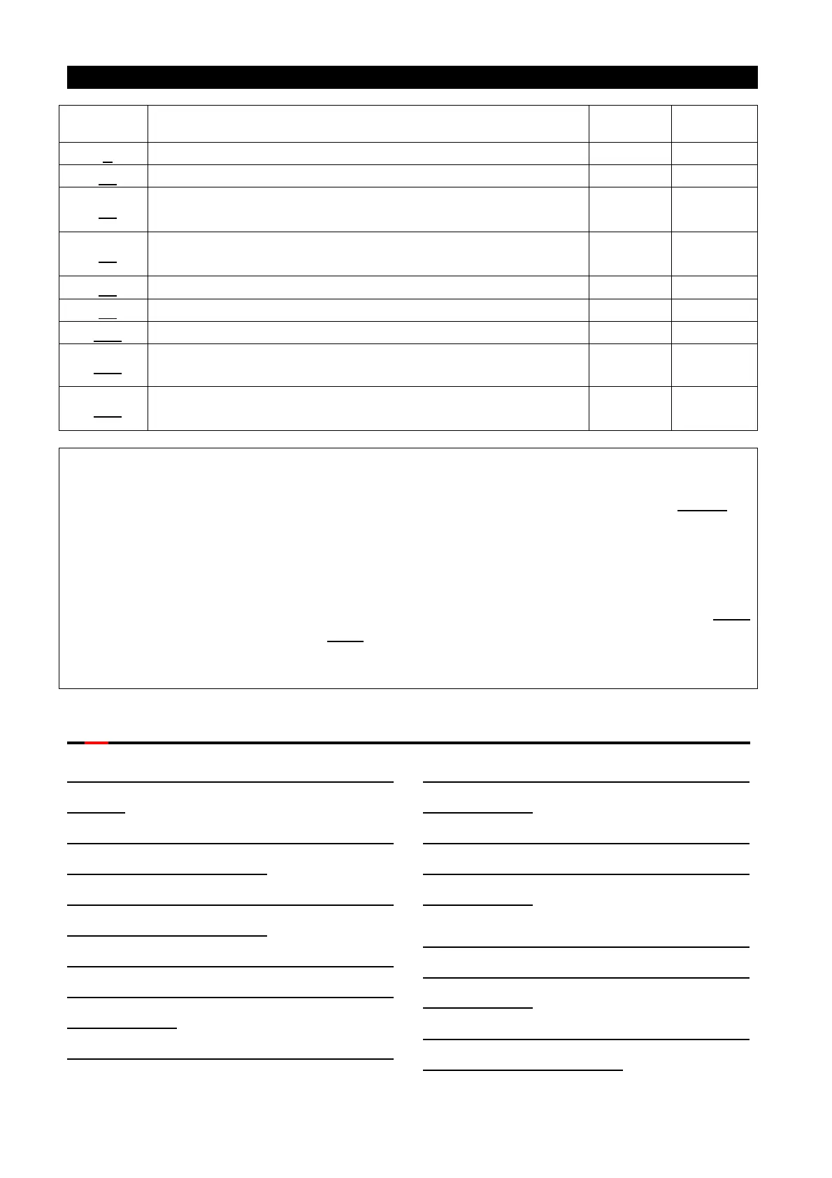
Parameter Description
Parameter Name
Acceleration / deceleration reference frequency
P.38
The maximum operation frequency (the target frequency
is set by the input signal of terminal 2-5)
1~650Hz 0.01Hz
P.39
The maximum operation frequency (the target frequency
is set by the input signal of terminal 4-5)
1~650Hz 0.01Hz
Frequency display reference
Stall prevention operation reduction starting frequency
P.307 Motor rated speed
1 r/min
P.509
The maximum operation frequency of terminal 1-5 (the
target frequency is set by the input signal of terminal 1-5)
1~650Hz 0.01Hz
Note: 1. Adjusting the default values from the table above would affect the acceleration/deceleration time,
the output voltage, the voltage signal rated frequency, etc., and bring problems to the customers.
In this case, the customers have to adjust the corresponding parameters, such as P.7, P.8
, to
more reasonable values.
2. If the customer would like to adjust the factory setting to 60Hz, please follow the following steps:
(1). Set P.189=0.
(2). Set P.998 to the factory default value (at this point, frequency-related parameters of the
inverter will be reset to 60Hz. The factory default value of P.189 is 0).For details on P.998
procedures, please refer to P.998 in Chapter 5.
3. To resume the 50Hz system, the customer should set P.189 to 1 and then follow Step 2 in Note 2
(at this time, the factory setting of P.189 is 1).
5.60 2-5 Terminal Input Signal (P.139, P.192~P.195, P.510~P.513)
P.139 “The bias rate of 2-5 voltage
signal”
P.192 “The minimum input positive
voltage of 2-5 terminal”
P.193 “The maximum input positive
voltage of 2-5 terminal”
P.194 “The setting corresponding to
the minimum positive voltage of
termianl 2-5”
P.195 “The setting corresponding to
the maximum positive voltage of
terminal 2-5”
P.510 “The setting corresponding to
the minimum negative voltage of
termianl 2-5”
P.511 “The setting corresponding to
the maximum negative voltage of
terminal 2-5”
P.512 “The minimum input negative
voltage of terminal 2-5”

 Loading...

