Shihlin Inverter Introduction
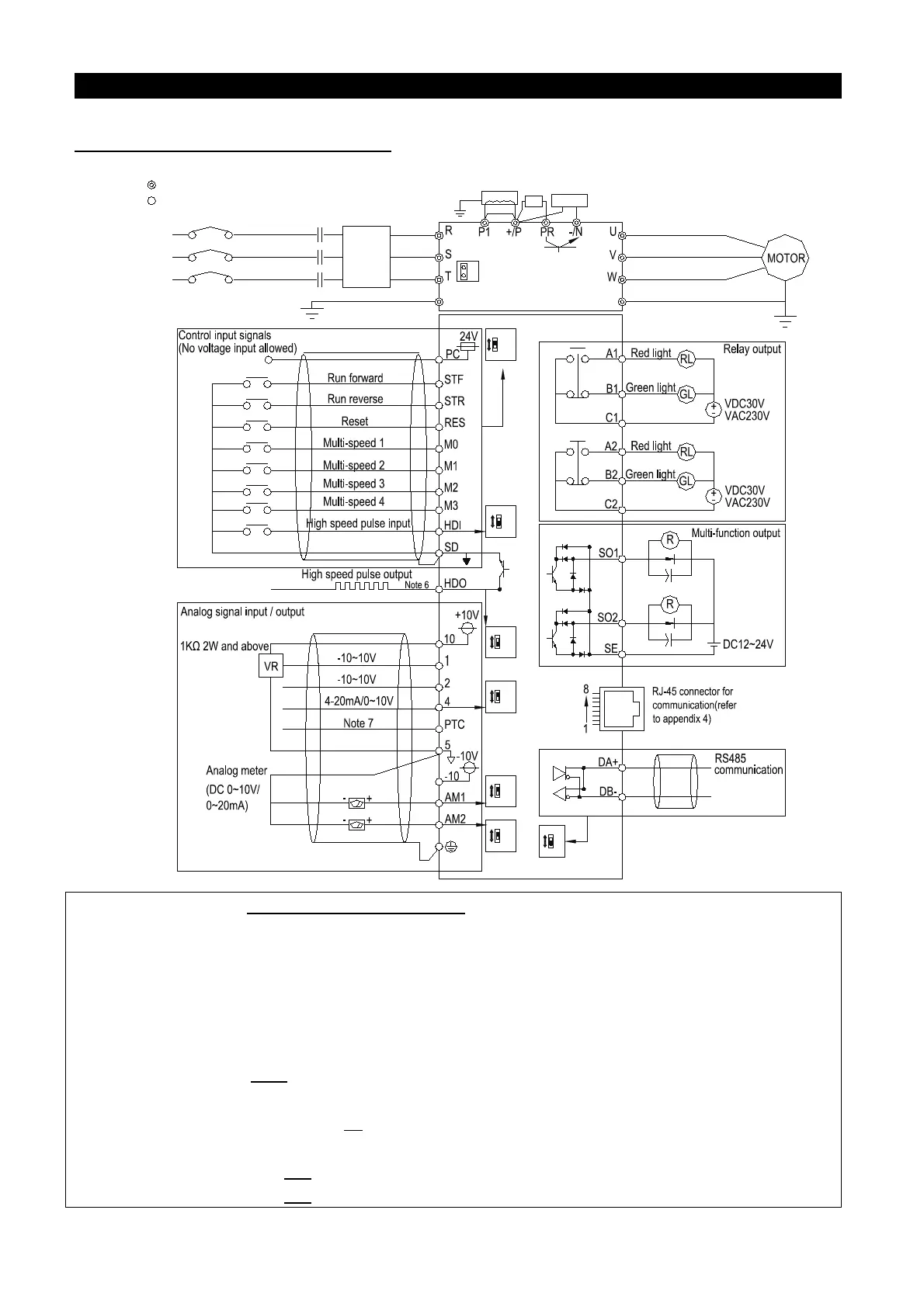
3.5.6 Terminal Wire Arrangement
SOURCE
SINK
R
Reserved
(
Jumper
:
ON
)
Removed (Jumper
:
OFF)
FILTER
SW4
4-20mA
0-10V
0-10V
0-20mA
0-20mA
0-10V
SW5
PG
HDI
120
OPEN
SW6
SW2
SW11
SW10
SW12
HDO
AM1
Main circuit terminals
Control circuit terminals
Three phase AC
power supply
A.C.
reactor
Main circuit
Control circuit
Note 5
Note 4
NFB/MCCB
BU
MC
JUMPER
Note: 1. Please refer to P.80~P.84, P.86, P.126, P.550(OH)of Chapter 5 for the applications of
external thermal overload relay.
2. Make sure that 10, -10, SD, SE, 5 and PC are not shorted each other.
3. The DC resistor between +/P and P1 is optional. Please short +/P and P1 when AC resistor is not
used.
4. The brake resistor connection approach between +/P and PR is for frames A and B only.
For connecting the brake unit of frame D, E, F to between +/P and -/N, please refer to terminal
arrangement in 3.4.5
5. Inverters corresponding to frame E、F have build-in DC reactors, you can also refer to DC
reactor specification on page 37
before adding DC reactors in addition.( When adding DC
reactors, please remove the short circuit piece between P1 and +/P.)
6. Please refer to page 100
for wiring of HDO.
7. Please refer to page 160 for wiring of PTC.

 Loading...

