Parameter Description
5.81 Feedback Control Parameters (P.350~P.359)
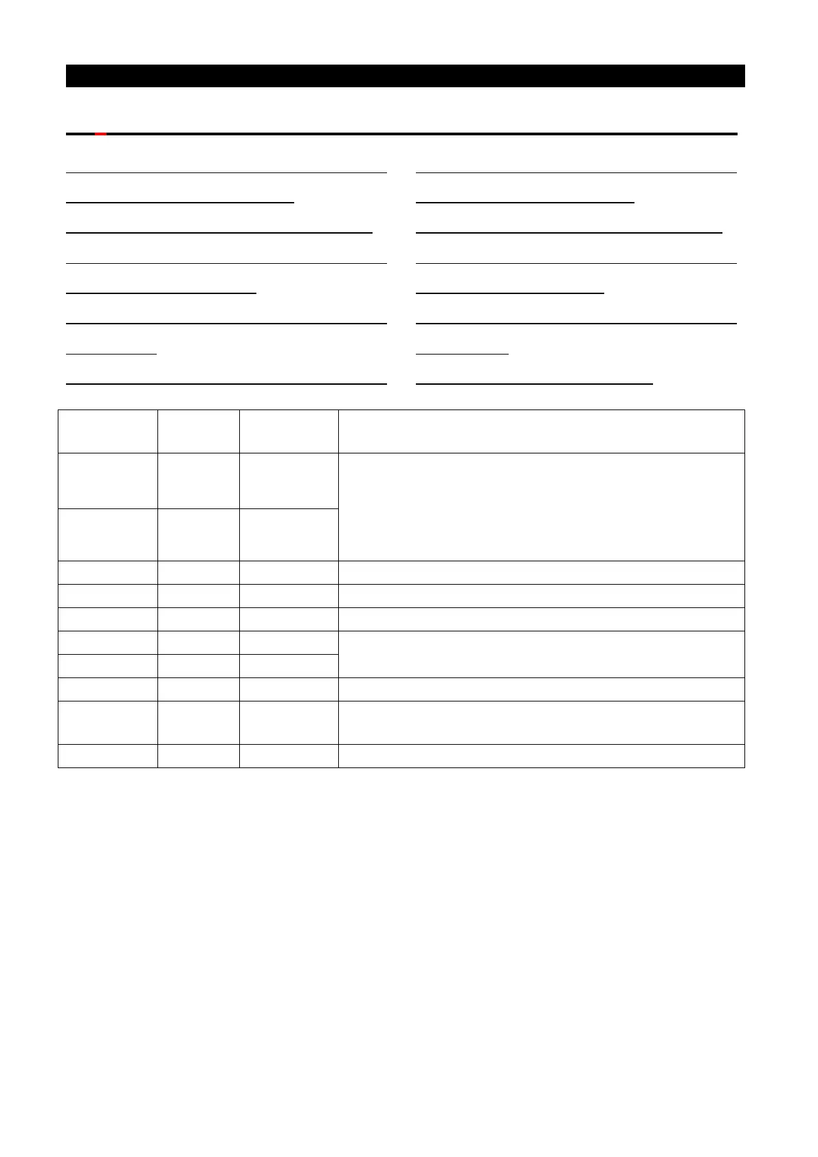
P.350 “Number 1 of pulses per
revolution of the encoder”
P.351 “Encoder input mode setup 1”
P.352 “PG signal abnormality (zero
speed) detection time”
P.353 “Motor over-speed detection
frequency”
P.354 “PG over-speed detection time”
P.355 “Number 2 of pulses per
revolution of the encoder”
P.356 “Encoder input mode setup 2”
P.357 “Dividing frequency output
setting (denominator)”
P.358 “Dividing frequency filter
coefficient”
P.359 “Electronic gear ratio”
Parameter
Remarks
P.350 2500 1~20000
P.350 and P.351 are used to set the encoder signal
which connects to the A1/B1 interface on PG03.
When the closed loop controls, the encoder signal for
feedback can only be connected to
P.351 0 0~4
P.353 4Hz 0~30Hz
P.355 and P.356 are used to set the encoder signal
which connects to the A2/B2 interface on PG03.
The multiple setting for PG03 feedback and output
P.358 0 0~255
The setting of PG03 dividing frequency filter
coefficient
<Setting>
• When the switch SW11 is set to PG, the terminal A2/B2 on PG03 card is valid.
• When using the PG card, P.350 and P.355 are applied for setting up the number of pulses
to be generated by the encoder per revolution of the motor. That is, the number of pulses
generated by one cycle of Phase A/Phase B. When carrying out PG feedback control, if
the detected frequency is 0, and with duration longer than the time set by P.352, and then
the PG card’s feedback signal is abnormal. The inverter will display alarm PG2 and stop
the operation. If PG signal abnormal (zero speed) detection time P.352 is set to 0, then
there is no PG card feedback signal abnormal function, i.e., no alarm PG2.
• When carrying out PG feedback control, if the difference between the detected frequency
and the output frequency exceeds P.353, and with duration longer than the set time
of P.354, then the speed deviation is too big. The inverter will display alarm PG3 and stop
the operation. If PG over-speed detection time P.354 is set to 0, then alarm PG3 function is

 Loading...

