Parameter Description
5.23Multi-function Output (P.40, P.85, P.120, P.129, P.130)
P.40 “Multi-function output terminal SO1-SE function selection”
P.85 “Function selection for multi-function relay A1-B1-C1”
P.120 “Output signal delay time”
P.129 “Function selection for multi-function output terminal SO2-SE”
P.130 “Function selection for multi-function relay A2-B2-C2”
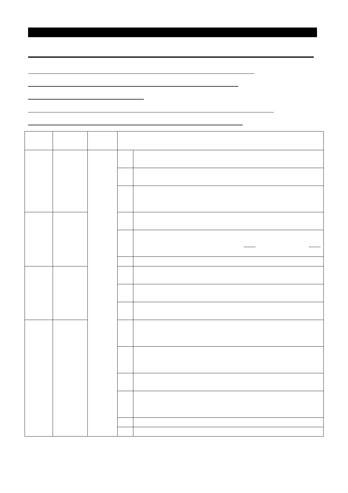
Parame
Factory
Setting
Remarks
40 1
0~10,
16~19
0
RUN (Inverter running): Signals will be sent out when the output
frequency is equal to or higher than the starting frequency.
1
SU (Reaching the output frequency): Signals will be sent out once
the output frequency reaches the set frequency.
2
FU (Output frequency detection): It is the output signal when
detecting the frequency exceeding the assigned frequency during
85 5
3
OL (Overload detection): It is the output signal when the current limit
4
OMD (Zero current detection): If the current output percentage of
the inverter is less than the set value of P.62 and has exceeded P.63
for a period of time, OMD will output the signal.
5
ALARM (Alarm detection): An alarm signal detected.
129 2
6
PO1 (Section detection): In the programmed operation mode, the
signal will be sent out at the end of each frequency operation.
7
PO2 (Periodical detection): In the programmed operation mode, the
signal will be sent out at the end of each operation cycle.
8
PO3 (Pause detection): In the programmed operation mode, the
signal will be sent out when the operation is suspended.
130 0
9
BP (Inverter output): Switch between the inverter operation and the
commercial power-supply operation function; in inverter operation,
BP will send out signals.
10
GP (Commercial power-supply output): Switch between the inverter
operation and the commercial power-supply operation function; in
the commercial power-supply operation, GP will send out signals.
16
FAN (Abnormal signal of fan): the output signal when the fan
detection return circuit has a problem.
17
RY (The accomplishment of inverter running preparation): the output
signal when resetting is accomplished after the inverter is powered
on. (the starting signal ON is in the started state)
Maintenance alarm detection
19
OL2(Over torque alarm output): refer to P.260 instruction

 Loading...

