Primary Operation
4.2 Basic Operation Procedures for Different Modes
4.2.1 Basic operation procedures for PU mode (P.79=0 or 1)
Step Description
1
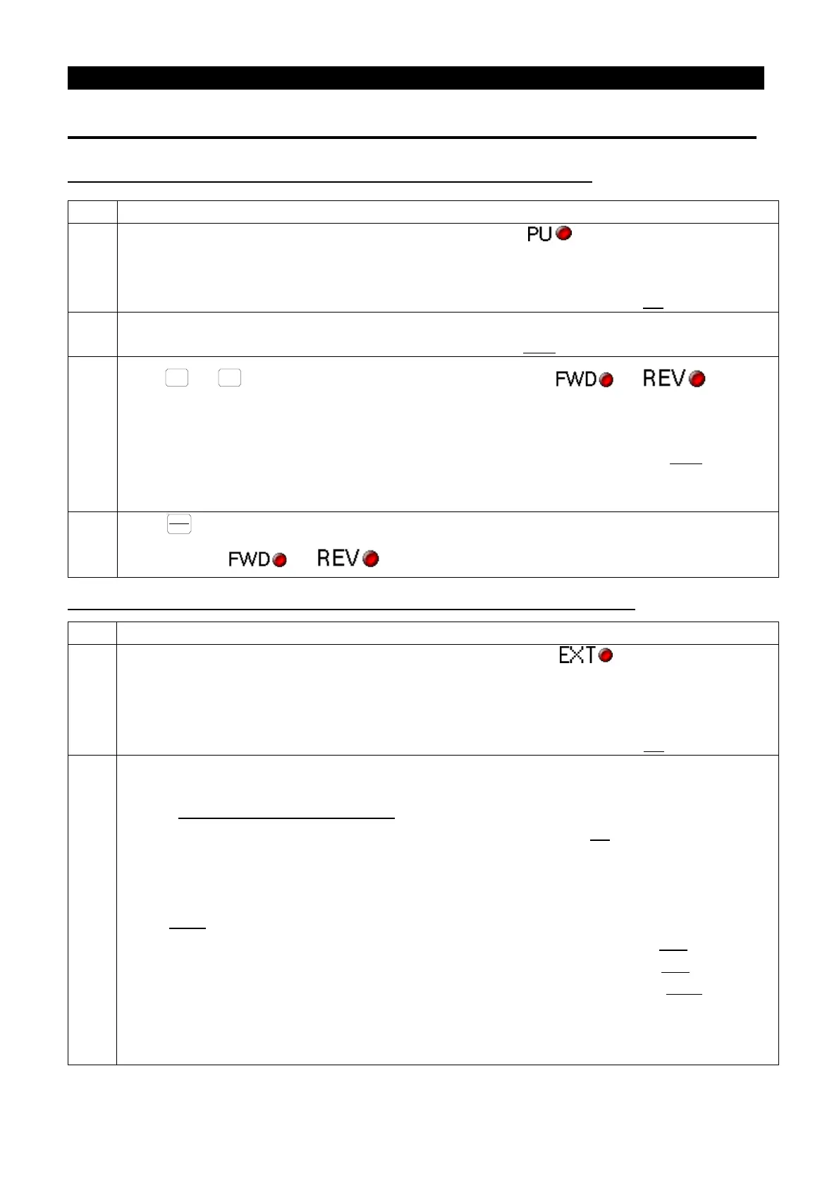
Change the operation mode to PU mode, and indicating lamp will light up.
Note: 1. When P.79=0, the inverter will first go into the external mode after the power is switched on
or the inverter is reset.
2. For selecting and switching the operation mode, please refer to Section 4.1
.
2
Enter the frequency setting mode and enter the target frequency into memory.
Note: For detailed setting procedures, please refer to Section 4.1.4.
3
Press
or
to run the motor. At this point, indicating lamp
or will light
up, indicating that the motor is running. The DU01 operation panel will automatically go into the
monitoring mode and display the current output frequency.
Note: 1. For detailed operation flow for the monitoring mode, please refer to Section 4.1.3
.
2. While the motor is running, the user can enter the frequency setting mode to change the
target frequency for regulating the motor speed.
4
Press
and the motor will begin to decelerate until it comes to a full stop.
Indicating lamp
or will not turn off until the inverter stops the output voltage.
4.2.2 Basic operation procedures for external mode (P.79=0 or 2)
1
Change the operation mode to external mode, and indicating lamp will light up.
Note: 1. When P.79=0, the inverter will first go into the external mode after the power is switched on
or the inverter is reset.
2. When P.79=2, external mode will be the default for the inverter.
3. For selecting and switching the operation mode, please refer to Section 4.1
.
2
The target frequency is set by external terminals (the default priority is from high to low).
If the programmable operating mode is chosen, please refer to the multi-
terminals P.80~P.84、P.86、P.126、P.550 in Chapter 5.
If the target frequency is set by multi-speed stage levels, please refer to P.4 in Chapter 5.
If the target frequency is set by the input signal of terminal A2/B2 on PG03, please refer to P.356 in
Chapter 5.
If the target frequency is set by PWM input pulse (switching SW11 to HDI in the meantime), please
refer to P.550
on Chapter 5.
If the target frequency is set by the input signal across terminal 2-5, please refer to P.38 in Chapter 5.
If the target frequency is set by the input signal across terminal 4-5, please refer to P.39 in Chapter 5
If the target frequency is set by the input signal across terminal 1-5, please refer to P.509
5.
If the target frequency is set by the high-speed pulse input across terminal HDI
HDI in the meantime), please refer to P.522 on Chapter 5.

 Loading...

