Parameter Description
P.255
P.256
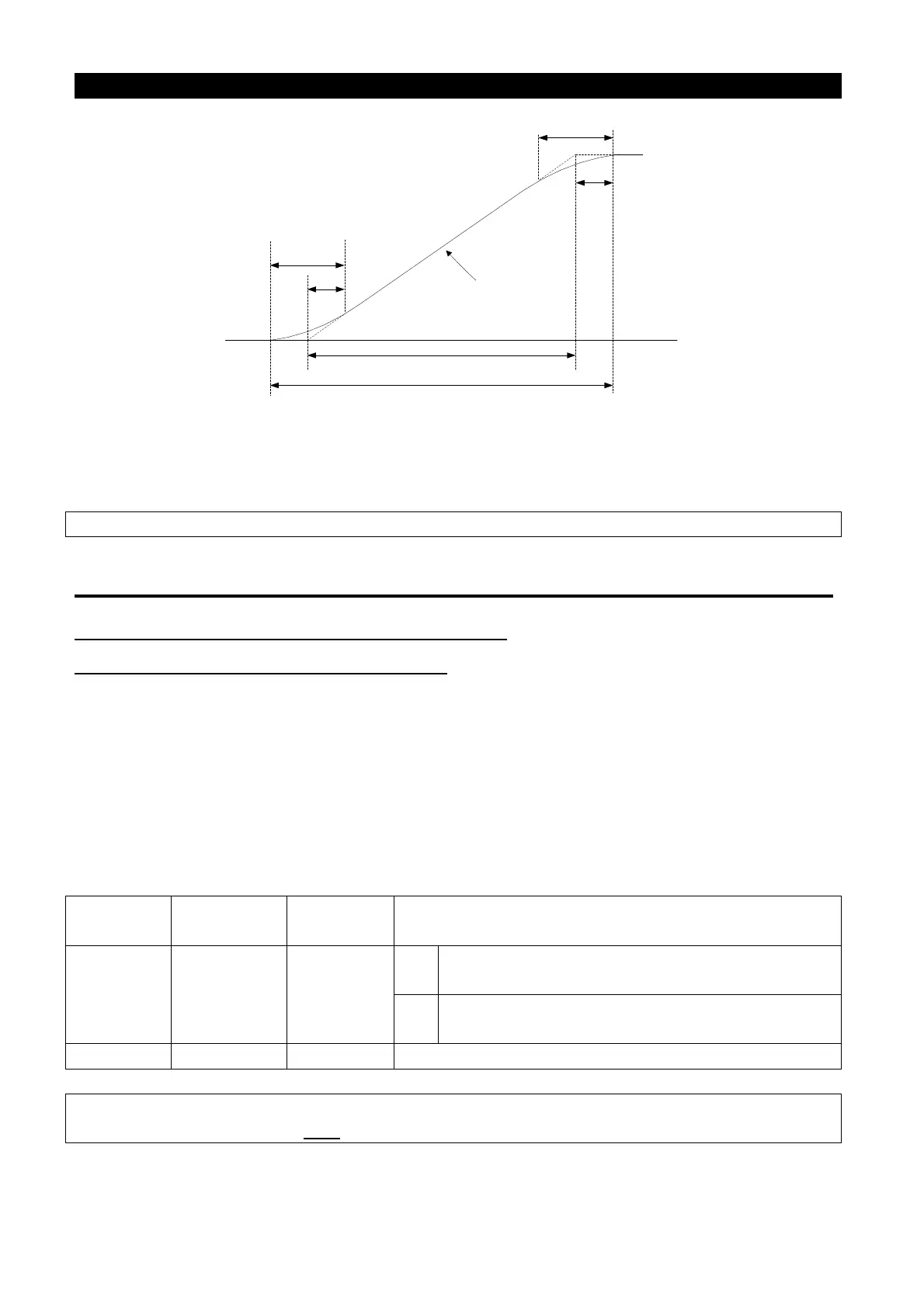
Starting frequency
(P.13)
Acceleration /
deceleration
reference frequency
(P.20)
P.256/2
P.255/2
T1
T2
Linear acceleration
(P.7 or P.44)
Fre1
Fre2
The acceleration time being set T1 = (P.20 - P.13) * P.7 / P.20
The actual acceleration time T2= T1 + (P.255 + P.256) * (P.20 - P.13) / 2 / P.20
So T1 = (60 - 0.5) * 5 / 60 = 4.96s (the actual acceleration time of linear acceleration)
The actual acceleration time T2 = 4.96 + (0.2 + 0.2) * (60 - 0.5) / 2 / 60 = 5.16s
Note: All calculations of acceleration/deceleration time are based on P.20.
5.14 Regenerative Brake (P.30 and P.70)
P. 30 “Regenerative brake function selection”
P. 70 “Special regenerative brake duty”
● At the moment of the inverter output frequency switching from high to low, the rotation
speed of the motor will be higher than the output frequency of the inverter due to load
inertia, resulting in generator effect. This effect will cause a high voltage between the
main-circuit terminals P and N, which will damage the inverter. Therefore, a proper brake
resistor shall be mounted between terminals P and PR to dissipate the feedback energy.
● There is a built-in transistor inside the inverter. The conducting time ratio of the transistor is
called “regenerative brake duty”. The higher the regenerative brake duty is, the more
energy the brake resistor consumes, and the stronger the brake capability is.
Parameter
Remarks
30 0 0~1
0
If regenerative brake duty is fixed at 3%,
parameter P.70 will be invalid.
1
The regenerative brake duty is the set value
of P.70.
Note: 1. In occasions where frequency starts or stops, a high capacity brake resistor is required.
2. Please refer to Section 3.7.3
for brake resistor selection.

 Loading...

