Parameter Description
Note: 1. When P.550 =57 and the toggle switch SW11 is switched to HDI, the HDI input function is valid.
2. The frequency computing method of HDI input signal is similar to 2-5 analog input, the formula is
P.1 * ((P.525-P.524)*(P.523-P.522)/(the input frequency– P.524) + P.522).
5.84 PTC(P.532~P.534)
P.532 “PTC filter coefficient”
P.533 “The process mode selection of PTC alarm”
P.534 “The percentage of PTC level”
Remarks
532 31 0~31 ----
533 0 0~3
0 Alarm and continue to run
1 Alarm and decelerate to stop
2 Alarm and stop freely
3 No alarm
534 0%
0~100
%
0 No PTC alarm
0.1%~1
00%
The motion level of PTC function
The 100% corresponds to the maximum analog input.
<Setting>
• P.532 is “PTC filter coefficient”, and it is used to filter out the operation frequency jitter
generated by component accuracy, noise or other factors. The larger the set value of
P.532 is, the better the filter ability is, and the slow response will be caused.
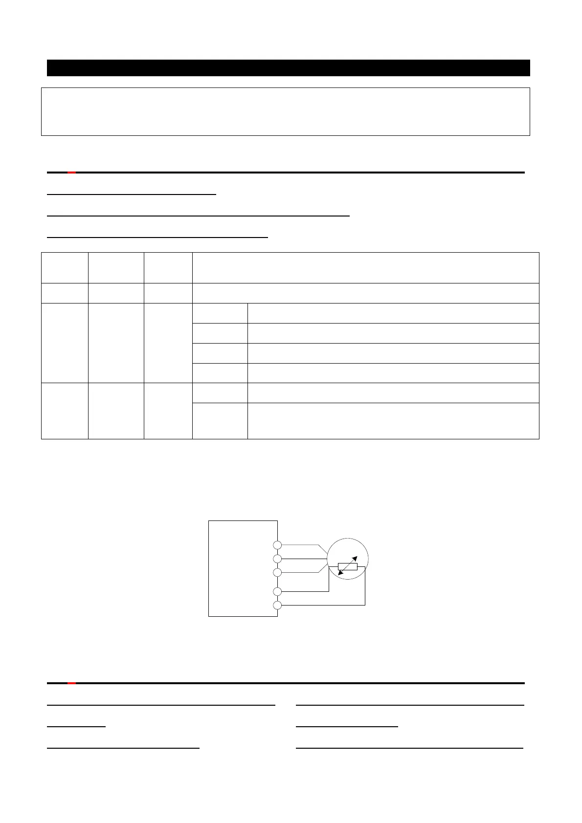
Inverter
U/T1
V/T2
W/T3
10
PTC
Motor
The diagram of PTC wiring
5.85 The tension control mode selection (P.600~P.603)
P.600 “The tension control mode
selection”
P.601 “The curling mode”
P.602 “Selection of inverse take-up
during roll-down”
P.603 “Mechanical transmission ratio”

 Loading...

