Shihlin Inverter Introduction
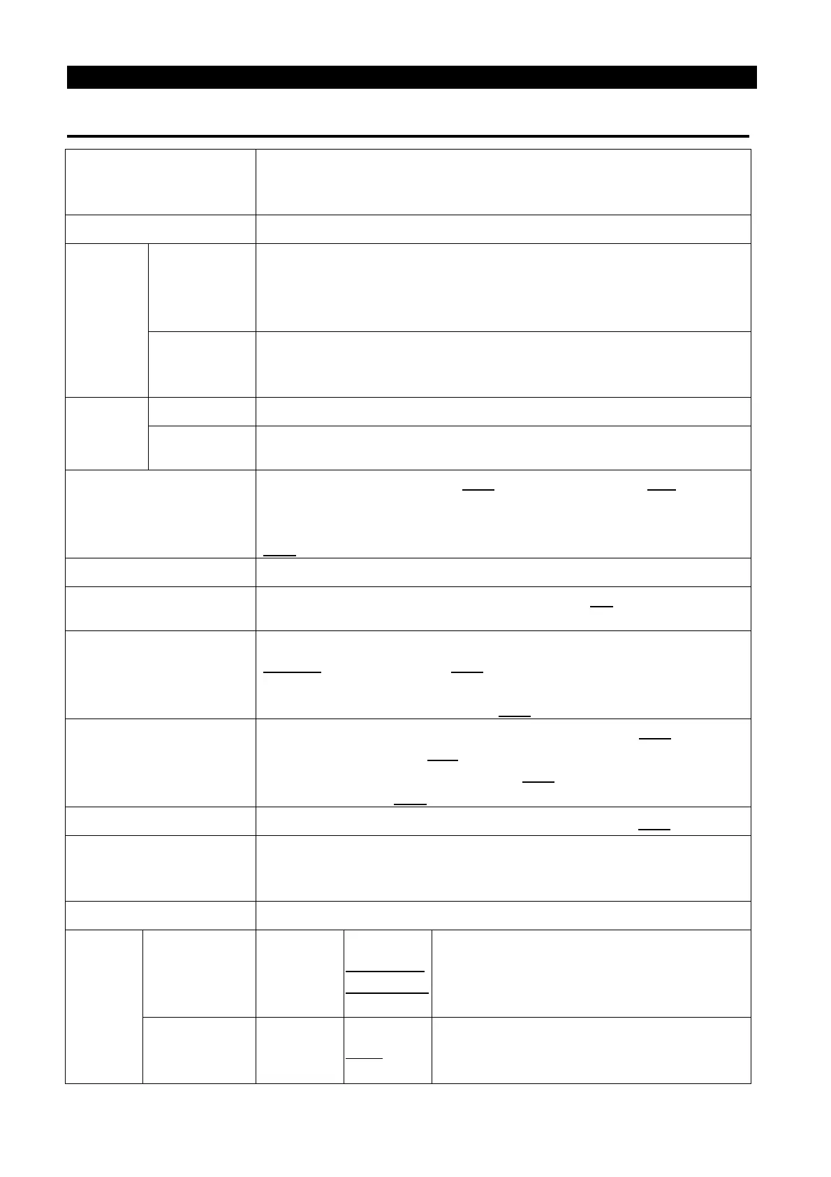
3.2 General Specification (Inverter Characteristics)
Control method
SVPWM control, V/F control, close-loop V/F
gene
ral flux vector control, sensorless vector control (SVC),
close-loop vector control (FOC+PG), torque control (TQC+PG).
Output frequency range 0.2~650Hz (The starting frequency setting range is 0~60Hz).
setting
resolution
Digita
If the frequency set value is below 100Hz, the resolution will be
0.01Hz.
If the frequency set value is above 100Hz, the resolution will be
0.1Hz.
Analog
setting
When setting DC 0~5V signals, the resolution will be 1/500;
When setting DC 0~10V or 4~
20mA signals, the resolution will be
1/1000.
Output
accuracy
Maximum target frequency ±0.01%.
Maximum target frequency ±0.5%.
Voltage/ Frequency
Base frequency voltage (P.19), base frequency (P.3) can be
arbitrarily set.
Constant torque model and applicable load model can be selected
(P.14).
Start torque
150% 0.5Hz (SVC) ,180% 0Hz (FOC+PG).
Torque boost
The torque boost setting range is 0~30% (P.0), auto boost, slip
compensation.
Acceleration /
deceleration curve
characteristics
The resolution (0.01s/0.1s) of acceleration/deceleration time
(P.7, P.8) is switched by P.21.
The setting range has 0~360s or
0~3600s for selection. And different
acceleration/deceleration
curve model can be selected by P.29.
DC braking
The DC braking action frequency is 0~120Hz (P.10); the DC
braking time is 0~60s (P.11).
The DC braking voltage is 0~30% (P.12).
Linear braking and idling
braking selection (P.71).
Stalling protection The stalling protection level can be set to 0~400% (P.22).
Target frequency setting
Operation panel setting, DC 0~5V/10V signal, DC -10~+
signal, DC 4~20 mA signal, multiple speed stage level setting
,
communication setting, HDI setting.
PID control Please refer to P.170~P.182 in chapter 4.
Input
terminals
Multi-
switching
signal input
2,STF,STR
,RES,M3)
P.80~P.84,
Motor starting (STF, STR), the second
function (RT), 16-
speed operation (RH,
RM, RL, REX), external thermal relay
(OH), reset (RES) and so on.
Pulse input HDI-SD
P.550
The terminal HDI can accept impulse
signal w
hich maximum frequency is 100
kHz.

 Loading...

