Parameter Description
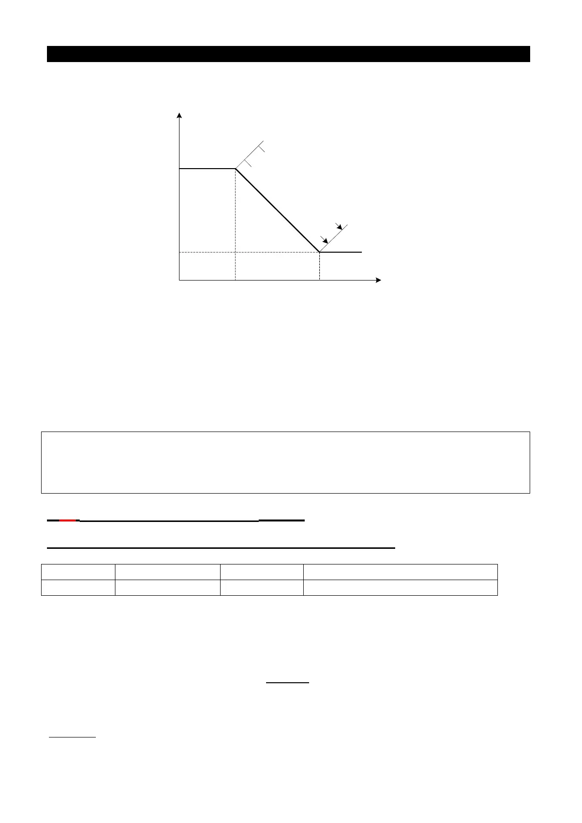
frequency is between the switching frequency 1 and the switching frequency 2, the two PI
parameters switch linearly.
Frequency
command
PI parameters
P323/P324
P325
P320/P321
0 P322
The coefficient P switches
from P.320 to P.323 linearly
The coefficient I switches
from P.321 to P.324 linearly
The diagram of the two PI parameter variation
• P.320/P.323 is used to set the proportion gain of speed control.(Set the value slightly larger
to better follow changes on the speed reference and to reduce speed change due to
external interference.)
• P.321/P.324 is used to set the integral time of speed control.(Due to external
interference-generated speed change, set the value smaller to shorten the time spent on
returning to the original speed).
Note: 1. Use P. 320/ P.3 23 to increase the set value of speed control gain can elevate the effecting time.
But a set value too high can generate vibration and noises.
2. Reduce speed control integral coefficient P.321/P.324 to shorten the time required to go back to
the original speed. But if the value is too small, overshoot can happen.
5.80 Torque limit range setting(P.326)
P.326“Torque limit range level under vector control ”
<Setting>
• When P.326=100%,the maximum output torque under the vector control is the motor rated
torque.
Motor rated torque calculation:
,
P(W) is on the basis of P.302, ω(rad/s) can be worked out according to the parameter P.307:
.

 Loading...

