Parameter Description
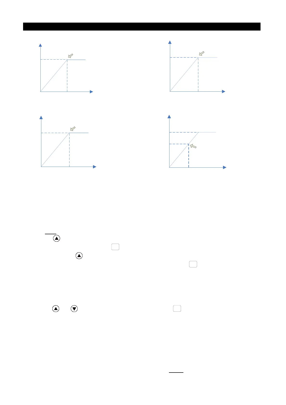
10V
0
AM1
Corresponding to 100% of
the function set by P.54
20mA
0
AM1
Corresponding to 100% of
the function set by P.54
Figure 1. AM1-5 output 0~10V voltage Figure 2. AM1-5 output 0~20mA current
20mA
4mA
AM1
Corresponding to 100% of
the function set by P.54
2300
Hz
0
1440Hz
FM Pulse frequency
Corresponding to 100% of
the function set by P.54
Figure 3. AM1-5 output 4~20mA current Figure 4. FM pulse output
• The voltage/current calibration procedures of AM1 terminal:
1. Set the toggle switch SW6 to 0~10V/0~20mA, then set P.64 at 0 or 2.
2. Insert an electric meter with a full graduation of 10V/20mA across terminal AM1 and
terminal 5. Set P.54 at 0. Calibrate the header due to accessory variation.
3. Set P.13 at 0. Start the motor. Fix the output frequency of the inverter to 0 Hz.
4. Press to adjust the value of P.190. The screen will display the accumulated output
bias voltage of AM1. Press
for more than 1 second, and the pointer will move
upward. Press to reduce the value of P.190, and the screen will display the
progressively decreased output bias voltage of AM1. Press
for more than 1second,
and the pointer will move downward. When the pointer is adjusted to 0, the calibration
of AM1 output bias voltage is completed.
5. Adjust and fix the output frequency of the inverter at 60 Hz.
6. Read the set value of P.191, and the screen will display the current output gain of AM1.
7. Press or
to adjust the value of P.191. Press
for more than 1 second, and
the pointer will move upward or downward. When the pointer moves to the full-scale
position, the calibration is completed.
• HDO terminal calibration procedures:
1. Wiring as figure 6 shown, and set P.64 at 1 and P.54 at 0. Calibrate the header for
accessory variation.
2. Start the motor and fix the output frequency of the inverter to 60 Hz.
3. When the motor runs steadily, read the set value of P.187. At this point, the screen will

 Loading...

