Parameter Description
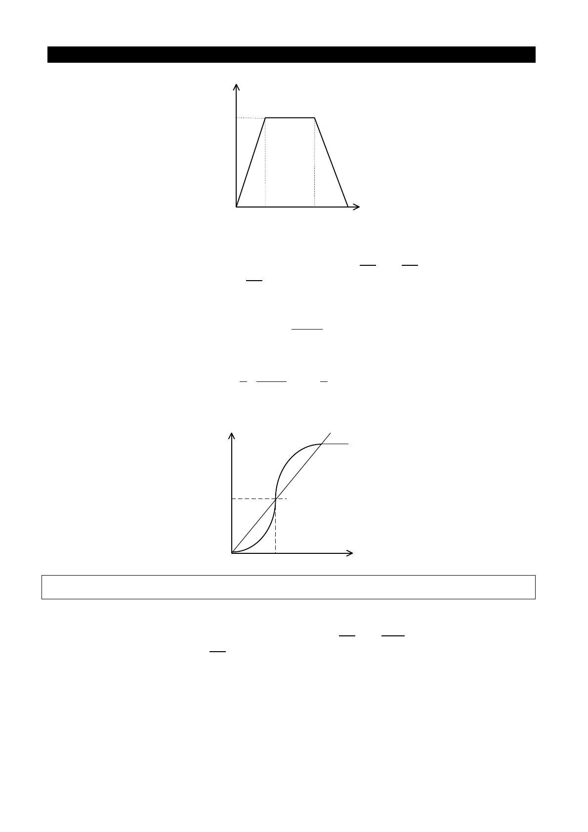
Output frequency
TimeP.7 P.8
Acceleration slope
Deceleration slope
P.20
• When P.29=1, “S pattern acceleration /deceleration curve 1”
An acceleration slope is constructed by the combination of P.7 and P.3. A deceleration slope
is constructed by the combination of P.8 and P.3.
The acceleration / deceleration curve has an S-shape change according to the
“acceleration / deceleration slope”. The S-shape equation between 0 and P.3 is:
3.)]
7.
90
cos(1[ P
P
t
f ×
×°
−=
The S-shape equation of P.3 or above is:
( )
7.
9
5
3.
7.
9
4
2
2
Pf
P
P
t ×+××=
t: time; f: output frequency
Acceleration slope
Output frequency
P.7
P.3
Time
Note: This pattern is applicable to main shafts of the working machines.
• When P.29=2, “S pattern acceleration /deceleration curve 2”
An acceleration slope is formed by the combination of P.7 and P.20. A deceleration slope is
formed by the combination of P.8 and P.20.
When the target frequency varies, the acceleration curve has an S-shape ascending
according to the “acceleration slope”. The deceleration curve on the other hand has an
S-shape deceleration according to the “deceleration slope”. As shown in the figure below,
when the setting value of the inverter is adjusted from f0 to f2, an S-shape acceleration is
undertaken once, and the time is P.7 x (f2-f0)/P.20. Then if the frequency is set from f2 to f3,
a second S-shape acceleration is experienced, and the time is P.7 x (f3-f2) / P.20.

 Loading...

