Parameter Description
1. SF RS-485 Communication interface constituents and wiring
● SF-GT RS-485 communication interface terminal arrangement
Terminal name explanation
DA+ Inverter transceiver +
DB- Inverter transceiver -
5
Signal ground
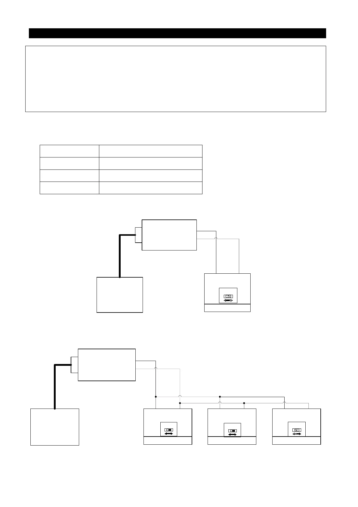
● Communication between the position machine and single inverter (take computer as an
example).
OPEN
SW10
120
computer
DA+
DB-
Station number 1
Inverter 1
RS- 485
DATA+
/
converter
RS- 232
DATA
-
RS
-
232 RS
-
485
5
● Communication between the position machine and multiple inverters (take computer as an
example).
computer
DA+
DB-
Station number 1
Inverter 1
RS- 485
DATA+
/
converter
RS- 232
DATA-
RS-485RS-232
5
Inverter 2 Inverter 3
DA+
DB-
5
DA+
DB-
5
OPEN
SW10
120
Station number 2 Station number 3
● SF-GT series inverters have two types of communication protocols: Shihlin communication
Note: 1. The number of inverters is practically determined by the wiring method and impedance matching.
If Modbus protocol is used, please set the value to a nonzero value.
2. If the frequency of communication error exceeds the set value of P.52, and P.153 is set to 0, the
alarm will go off and display OPT.
3. When P.53=99999, there is no time limit.
4. Modbus protocol. Displayed according to the starting bit, the data bit, parity check bit, and the
stop bit. N: no parity check. E: 1-bit parity check. O: 1-bit odd parity check.

 Loading...

