Parameter Description
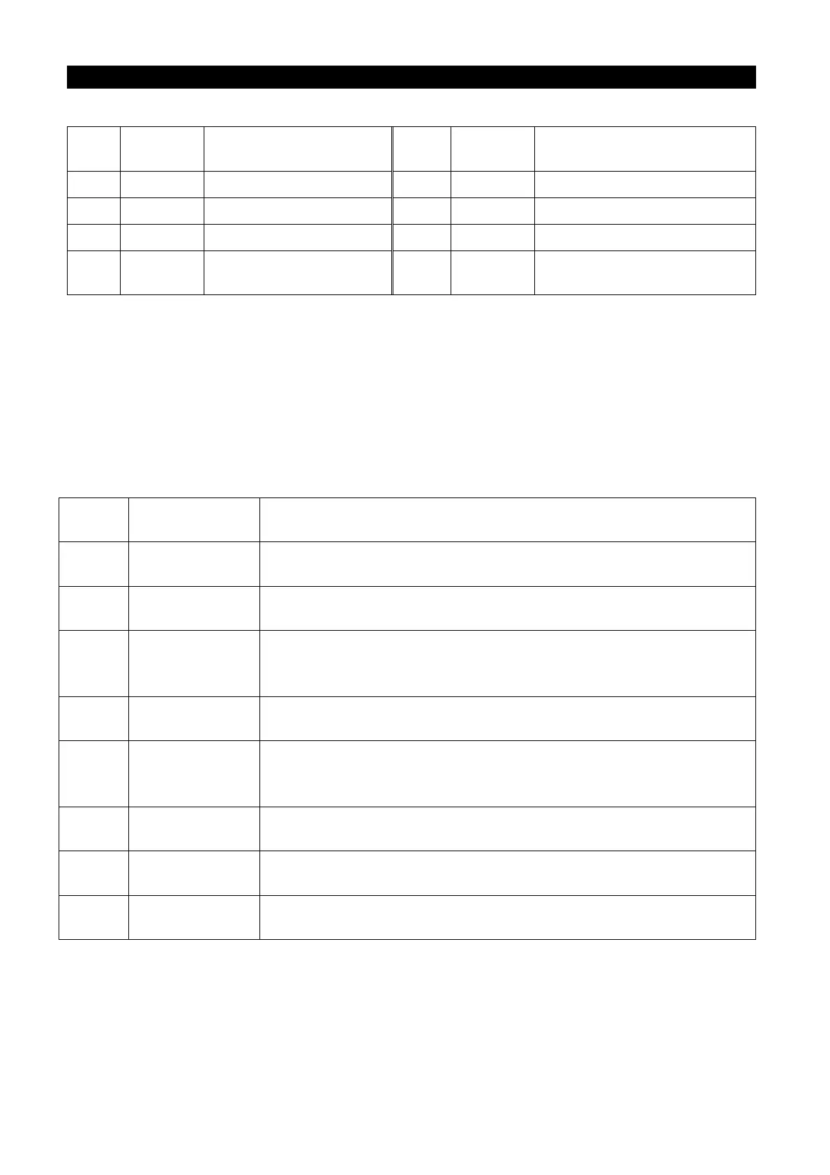
*1). Control code
signal
ASCII
Code
Content signal
ASCII
Code
Content
NUL H00 NULL(Empty) ACK H06 Acknowledge(No data error)
STX H02 Start of Text(Data begin) LF H0A Line Feed(Change line)
ETX H03 End of Text(Data end) CR H0D Carriage Return
ENQ H05
Enquiry(Communication
request)
NAK H15
Negative Acknowledge
(Data errors)
*2). Set the waiting time between 0 and 15 with a 10ms unit. Example: 5 50ms
*3). End symbol (CR, LF codes)
When carrying out data communication from the position machine to the inverter, CR and
LF codes at the end of the text are automatically set according to method of the position
machine. At this time, the inverter has to be set according to the position machine, too. If
only CR is selected, only one register will be occupied; if both CR and LF are selected,
two registers will be occupied.
*4). Unit: 0---> Unit 1, 1---> Unit 0.1, 2---> Unit 0.01, 3---> Unit 0.001
*5). Error code
Error
Error item Communication error and abnormality
H01 Error
The parity check of the data received by the inverter is different
from the parity check set initially.
H02
The Sum Check calculated by the inverter according to the
received data is different from the received Sum Check.
H03
Communication
protocol error
The syntax of the data received by the inverter has errors. The
data is not completely received during the assigned period of
time. CR and LF codes are different from the initial setting.
H04 Frame error
The stop bit of the data received by the inverter does not match
to the stop bit set initially.
H05 Overflow error
When the inverter is receiving data, the position machine sends
the next set of data before the inverter finishes receiving the
H0A
The running inverter or the operation of the inverter disqualifies
the requirements of the mode setting.
H0B
The user assigns a reference code that cannot be processed by
the inverter.
H0C
Data range
When setting the parameters and frequencies, the set values are
outside the set range of the data.
*6). When the parameter has the characteristics of 99999, the write-in or read-out of 99999
will be replaced by HFFFF.
*7). Request the sum check code
The converted ASCII codes of the data are summed up in binary digit format. The lower
bits (the lower eight bits) of the result (the sum) converted into ASCII binary digits

 Loading...

