Parameter Description
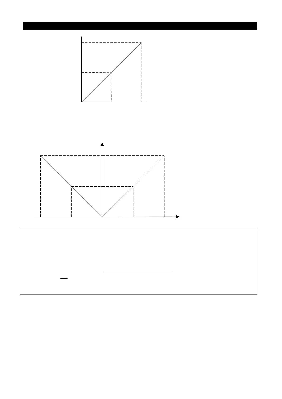
0V
5V
10V
0Hz
60Hz
30Hz
Max output
frequency
Parameter setting:
P. 38 = 60 Hz Max operation frequency
P.500 = 1 Frequency command is selected
P. 73 = 1 Voltage signal selection
Example 2: The value of P.73 needs to be changed if the terminal 2-5 connects to negative
voltage. The frequency arithmetic is the same as positive voltage and the
rotation direction is invariant.
0V
Max output
frequency
60Hz
30Hz
0Hz
5V
10V
-5V-10V
Parameter setting:
P.38 = 60Hz Max operation
frequency
P.73 = 5 voltage signal selectin
P.500 = 1 frequency command is
selected
Note: 1. In “External mode", “combined mode 2” or “combined mode 4”, the target frequency of the
inverter will be determined by the signal between 1-5/2-5/4-5 terminal when RH, RM, RL and
REX are all “off.” (the default priority is 2-5>4-5>1-5, please refer to P.500~P.502)
2. RL, RM, RH, REX, AU, RT and RUN mentioned at the end of this section are the function names
of “multi-function control terminal”. For the options and functions of multi-
terminals, please refer to P.80~P.84, P.86, P.12 6, P.550. For related wiring, please refer to
Section 3.5.
3. The selection of range of voltage signal sampling across terminal 2-5 by parameter P.73 will
affect the parameters value of 2-5 terminal input signal in section 5.56.

 Loading...

