Configuring reduced resolution
R
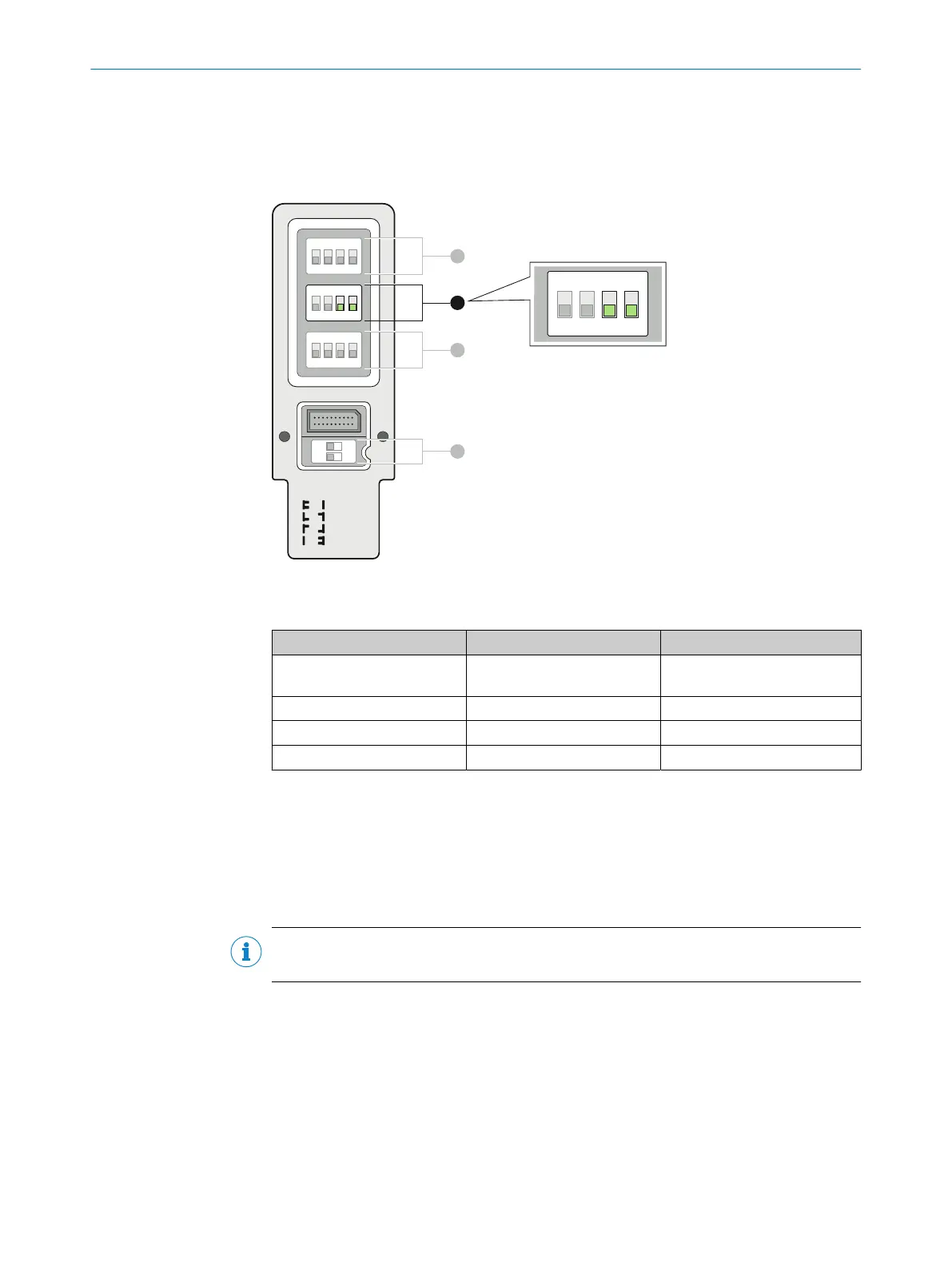
educed resolution is configured using DIP switches 3 and 4 (row B) on the system plug
of the receiver.
The reduced resolution configuration is taken on by all guest devices in a cascade.
OFF
uncoded
code 1
code 2
rev.conf.
ON
1 2 3 4
O F F
1 2 3 4
O F F
1 2 3 4
O F F
1
O N
2
A
B
C
D
1 2 3 4
O F F
Figure 60: DIP switch for reduced resolution on SP2 system plug
T
able 36: DIP switches and reduced resolution
DIP switch 3 (row B) DIP switch 4 (row B) Function
Off Off Reduced resolution inactive
(de
livery condition)
Off On 1 beam
On Off 2 beams
On On Not allowed
Note on configuration
b
Chec
k the parity after setting the DIP switch, see "Checking the parity", page 102.
7.9 Configuring smart presence detection
Important information
NOTE
Smar
t presence detection is only configured on the receiver of a host system.
Prerequisites
•
SP2 s
ystem plug
•
Cascade
Configuring smart presence detection
Smar
t presence detection is configured using DIP switch 1 (row C) on the system plug
of the receiver.
The smart presence detection configuration is taken on by all guest devices in a
cascade.
7 C
ONFIGURATION
100
O P E R A T I N G I N S T R U C T I O N S | deTec4 8021645/1EB0/2022-04-28 | SICK
Subject to change without notice