Outputs OSSD 1 and OSSD 2 carry voltage, the RLY3-OSSD1 is switched on. When
t
he protective field is interrupted, the OSSD 1 and OSSD 2 outputs switch the
RLY3-OSSD1 off.
•
F
ault analysis
Cross-circuits and short-circuits of the OSSDs are recognized and lead to the
loc
king state (lock-out). The malfunction of the RLY3-OSSD1 is detected. The
shut-down function is retained. Manipulation (e.g., jamming) of the S1 pushbutton
prevents the output current circuits from being enabled.
T-connector, RLY3-OSSD2 safety relay, with restart interlock and external device monitoring (EDM)
System connection
deTec4
0 V
3) P
ELV
+24 V
MFP 1
OSSD 1
OSSD 2
0 V
+24 V DC
5
3
4
2
1
k2
z
k1 k2
k1
z
x y
x y
0 V
MFP 1
In 1
+24 V DC
In 2
5
3
2
1
4
5
3
4
2
1
5
3
4
2
1
5
3
4
2
1
E324375/00/2021-09-27
r
s
F2 F1
K2 K1
R1 Y1 Y2 24A2 14
S1 I1 I2 23A1 13
RLY3-OSSD2
k2
k1
2)
1)
S1
L+
L–
System connection
F0
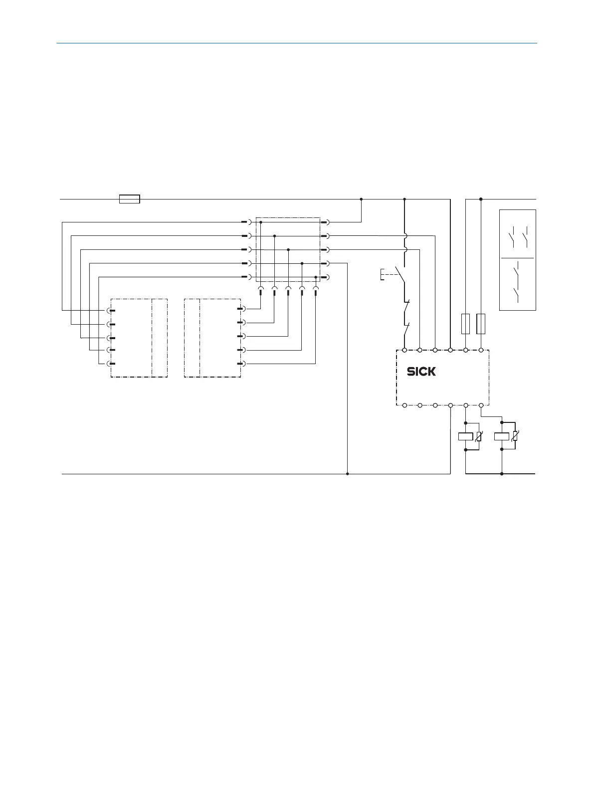
Figure 39: Connection diagram: 5-pin, T-connector, RLY3-OSSD2, with restart interlock and external device monitoring (EDM)
1) Output circuits. These contacts must be incorporated into the control such that the
d
angerous state is brought to an end if the output circuit is open. For categories 4 and
3, they must be incorporated on two channels (x, y paths). Single-channel incorporation
into the control (z path) is only possible with a single-channel control and taking the risk
analysis into account.
2) External device monitoring is only static.
3) SELV/PELV safety extra-low voltage.
•
T
ask
Connection of a deTec4 safety light curtain to a RLY3-OSSD2 safety relay. Oper‐
a
ting mode: With restart interlock and external device monitoring (EDM). The
T-connector establishes a connection between the sender and the receiver.
•
Mode of oper
ation
When the protective field is clear, the OSSD 1 and OSSD 2 outputs carry voltage.
T
he system can be switched on when K1 and K2 are in a fault-free de-energized
position. The RLY3-OSSD2 is switched on by pressing S1 (pushbutton is pressed
PROJECT PLANNING 4
8021645/1EB0/2022-04-28 | SICK O P E R A T I N G I N S T R U C T I O N S | deTec4
67
Subject to change without notice