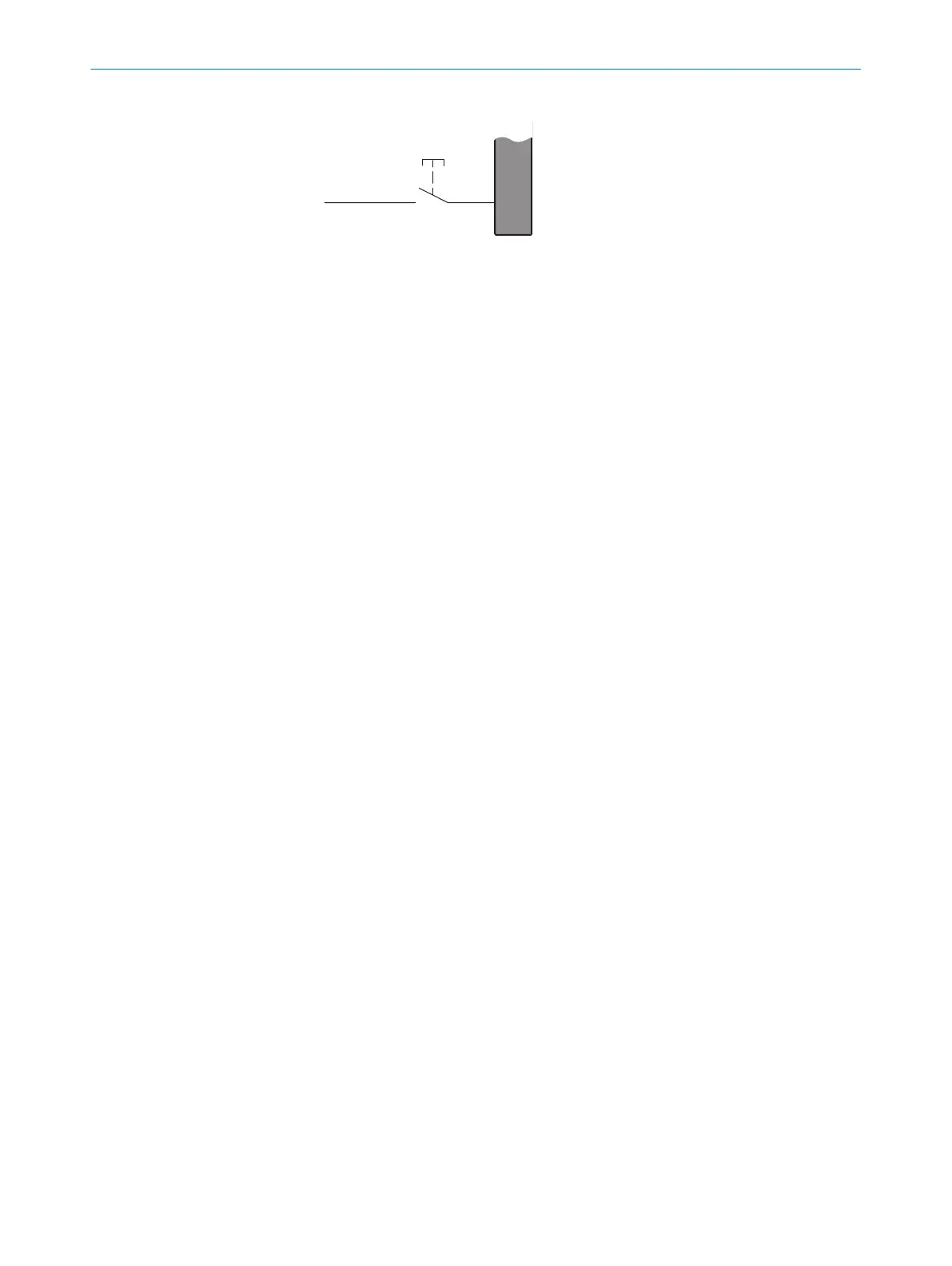
Figure 33: Electrical diagram of the reset device
Using an integrated restart interlock
T
he restart interlock is configured once the reset pushbutton has been connected.
When the restart interlock is configured, the application diagnostic output located on
the same plug connector as the reset pushbutton signals when the reset pushbutton
needs to be pressed.
The following applies to the restart interlock:
•
If the protective field is clear once the machine has been switched on or following
an interruption, the OSSDs do not switch to the ON state
•
If someone presses the reset pushbutton and then lets go of it when the protec‐
tive field is clear, the OSSDs switch to the ON state
•
The machine may not restart yet. The operator must also press the machine start
button after having pressed the reset pushbutton.
Single system
Onl
y one reset pushbutton may be connected to a single safety light curtain.
Connection options of the reset pushbutton in the single system:
•
M12, 8-pin system connection
•
Extension connection on the receiver
Cascade
A t
otal of just one reset pushbutton may be connected to a cascade comprising two or
three safety light curtains.
Connection options of the reset pushbutton in a cascade:
•
M12 system connection, 8-pin at the receiver of the host device
•
Extension connection at the last receiver of the guest device
Further topics
•
"C
onfiguring the restart interlock", page 103
4.4.2 External device monitoring (EDM)
Overview
T
he safety light curtain has internal external device monitoring.
The external switching elements (external device monitoring, EDM) must be inspected
in line with the regulations which apply at the place of installation or the required
reliability of the safety function.
External device monitoring (EDM) monitors the status of downstream contactors.
Prerequisites
•
P
ositively guided contactors are used for shutting down the machine.
PROJECT PLANNING 4
8021645/1EB0/2022-04-28 | SICK O P E R A T I N G I N S T R U C T I O N S | deTec4
57
Subject to change without notice