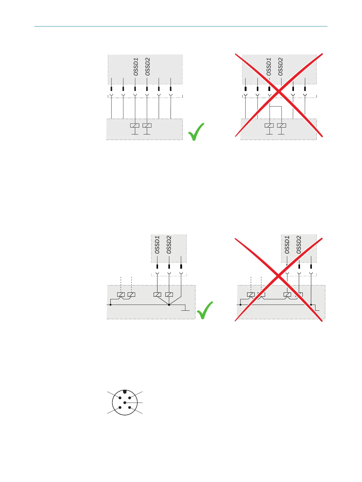
Example: Isolated connection of OSSD1 and OSSD2
Figure 49: Dual-channel and isolated connection of OSSD1 and OSSD2
Avoiding any potential difference between load and protective device
If y
ou connect loads to the output signal switching devices (switching outputs) that
then also switch if controlled with negative voltage (e.g., electro-mechanical contactor
without reverse polarity protection diode), you must connect the 0 V connections of
these loads and those of the corresponding protective device separately and also
directly to the same 0 V terminal strip. In the event of a fault, this is the only way to
ensure that there can be no potential difference between the 0 V connections of the
loads and those of the corresponding protective device.
Figure 50: No potential difference between load and protective device
Further topics
•
"Int
egration in electrical control", page 54
•
"Technical data", page 140
6.2 System connection (M12, 5-pin)
Figure 51: System connection (male connector, M12, 5-pin)
ELECTRICAL INSTALLATION 6
8021645/1EB0/2022-04-28 | SICK O P E R A T I N G I N S T R U C T I O N S | deTec4
87
Subject to change without notice