Prerequisites
•
SP2 s
ystem plug
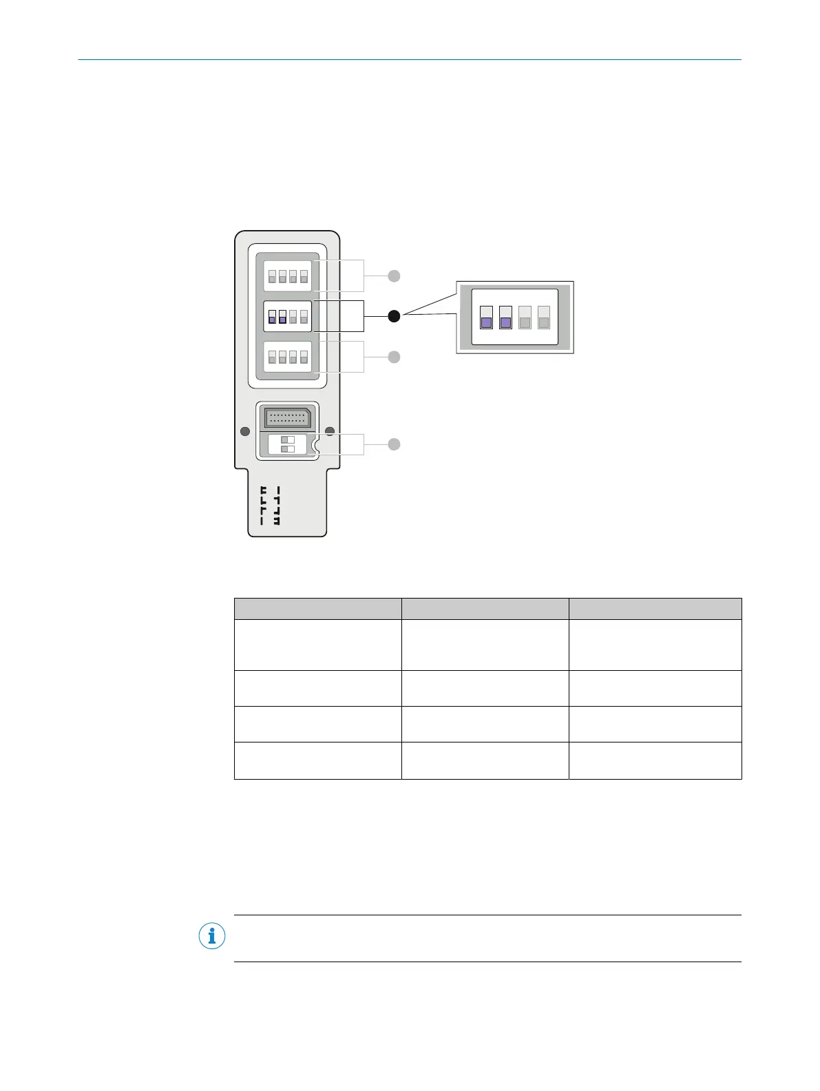
Configuring the scanning range
T
he scanning range of the safety light curtain is configured using DIP switches 1 and 2
(row B) on the system plug of the receiver.
The scanning range configuration is taken on by all guest devices in a cascade.
OFF
uncoded
code 1
code 2
rev.conf.
ON
1 2 3 4
O F F
1 2 3 4
O F F
1 2 3 4
O F F
1
O N
2
A
B
C
D
1 2 3 4
O F F
Figure 59: DIP switches for scanning ranges on SP2 system plug
T
able 35: DIP switches and scanning range
DIP switch 1 (row B) DIP switch 2 (row B) Function
Off Off Automatic calibration of the
pr
otective field width (delivery
condition)
Off On Dynamic protective field width
(small range)
On Off Dynamic protective field width
(medium range)
On On Dynamic protective field width
(
large range)
Note on configuration
b
Chec
k the parity after setting the DIP switch, see "Checking the parity", page 102.
7.8 Configuring reduced resolution
Important information
NOTE
R
educed resolution is only configured on the receiver of a single or host system.
Prerequisites
•
SP2 s
ystem plug
CONFIGURATION 7
8021645/1EB0/2022-04-28 | SICK O P E R A T I N G I N S T R U C T I O N S | deTec4
99
Subject to change without notice