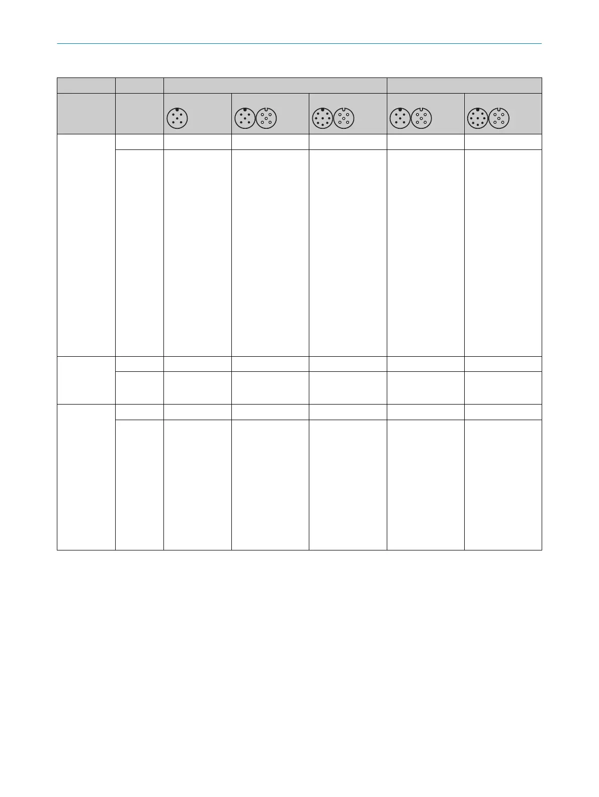
Table 6: Use of system plugs in a cascade
SP1 system plug type code SP2 system plug type code
1000 1100 1300 2100 2300
Host Sender
–
✓
✓
1)
– –
Receiver –
✓
F
unctions at the
host
•
Beam coding
✓
Functions at the
host
•
Beam coding
•
Restart inter‐
lock
•
External device
monitoring
•
Application
diagnostic out‐
put
✓
Functions at the
host
•
Beam coding
•
Reduced reso‐
lution
•
Dynamic pro‐
tective field
width
•
Smart pres‐
ence detection
✓
Functions at the
host
•
Beam coding
•
Reduced reso‐
lution
•
Dynamic pro‐
tective field
width
•
Restart inter‐
lock
•
External device
monitoring
•
Application
diagnostic out‐
put
•
Smart pres‐
ence detection
First guest
(
for cascade
with 2 guest
devices)
Sender –
✓
– – –
Receiver –
✓
– – –
Last guest Sender
✓
✓
2)
– – –
Receiver
✓ ✓
F
unctions at the
last guest
•
External device
monitoring
•
Restart inter‐
lock
•
Application
diagnostic out‐
put
•
IO-Link
– – –
✓
System plug suitable.
–
System plug not suitable. An SP1 system plug must be used on the receiver of a guest system as well as on the sender of a host system
and gue
st system.
1)
At the sender, the 8-pin system connection is solely for the purposes of providing standardized wiring. It is particularly recommended if the
8-pin system connection at the receiver is used and the sender and receiver are connected to each other via a T-connector.
2)
If a sender does not have an additional guest connected to it, the extension connection has no function and must be sealed with a
protective cap.
3.2.19 Flexible control cabinet cabling and status indication on both sides
The safety light curtain can be connected to the control cabinet in different ways as
r
equired:
•
Separate connecting cables for sender and receiver
•
Separate connecting cables for sender and receiver with connection in the control
cabinet
•
Connection of sender and receiver via a T-connector, shared 5-pin or 8-pin con‐
necting cable to the control cabinet
3 P
RODUCT DESCRIPTION
20
O P E R A T I N G I N S T R U C T I O N S | deTec4 8021645/1EB0/2022-04-28 | SICK
Subject to change without notice