7.5 Configuring beam coding
Overview
T
he beam coding “uncoded” allows for particularly short response times.
To protect against interference from systems in close proximity to each other, code 1
and code 2 must be used
The beam coding must be the same for the sender and receiver.
In a cascade, the beam coding is set on the sender and receiver of the host device and
taken on by all guest devices. Deviating settings for the guest devices are ignored.
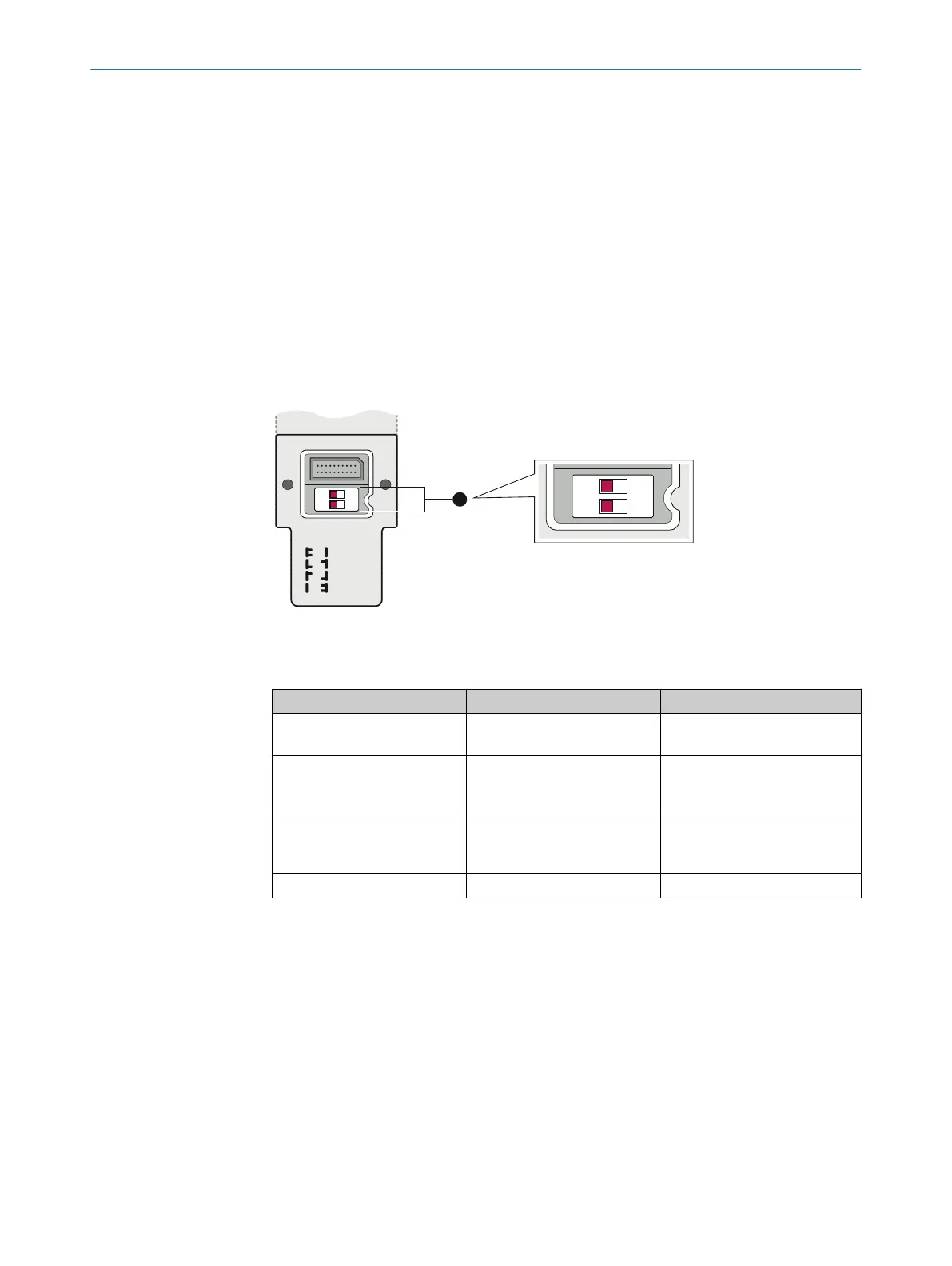
Configuring beam coding
T
he beam coding is configured using 2 DIP switches. The DIP switches are located on
the inside of the system plug.
OFF
uncoded
code 1
code 2
rev.conf.
ON
1
O N
2
D
Figure 57: Configuring beam coding
T
able 33: DIP switches and beam coding
DIP switch 1 (row D) DIP switch 2 (row D) Function
Off Off Uncoded (fast response time,
de
livery status)
On Off Code 1 (protection against
interference from systems in
close proximity to each other)
Off On Code 2 (protection against
interference from systems in
close proximity to each other)
On On Reset to factory settings
The beam coding is indicated when the safety light curtain is switched on:
•
U
ncoded: the field indicator does not flash yellow
•
Code 1: the field indicator flashes yellow once
•
Code 2: the field indicator flashes yellow twice
Complementary information
You can also change the beam coding later. You do not need to reset the safety light
curtain to the factory settings to do this.
During the first change to the beam coding, diagnostic LED 3 flashes white for 3 s.
Afterwards, the diagnostic LED lights up white steadily.
Beam coding does not have to be taken into account for the parity test.
7 C
ONFIGURATION
96
O P E R A T I N G I N S T R U C T I O N S | deTec4 8021645/1EB0/2022-04-28 | SICK
Subject to change without notice