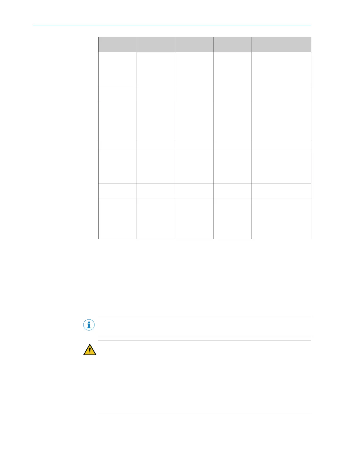
DIP switch 1
(r
ow A)
DIP switch 2
(row A)
DIP switch 3
(row A)
DIP switch 4
(row A)
Function
Off On Off On Cross-muting with muting
signal 1 on system con‐
nection In4 and muting
signal 2 on extension
connection In2
Off On On Off Partial blanking based on
cr
oss-muting
Off On On On Partial blanking based on
cross-muting with muting
signal 1 on system con‐
nection In4 and muting
signal 2 on extension
connection In2
On Off Off Off Exit monitoring
1)
2)
3)
On Off Off On Exit monitoring with mut‐
in
g signal 1 on system
connection In4 and mut‐
ing signal 2 on extension
connection In2
1)
2)
3)
On Off On Off Partial blanking based on
exit monitoring
1)
2)
3)
On Off On On Partial blanking based on
exit monitoring with mut‐
ing signal 1 on system
connection In4 and mut‐
ing signal 2 on extension
connection In2
1)
2)
3)
1)
Muting hold time of 4 s.
2)
Muting end by ESPE active.
3)
Muting end delay of 200 ms.
Note on configuration
b
Chec
k the parity after setting the DIP switch, see "Checking the parity", page 102.
7.7 Configuring the scanning range
Important information
NOTE
T
he scanning range is only configured on the receiver of a single or host system.
DANGER
Incor
rect scanning width setting for dynamic protective field widths in the case of
devices with a resolution of 14 mm
Detection capability is no longer guaranteed. Persons and parts of the body to be
protected may not be detected.
b
In cases where the actual protective field width may be less than 1 m, configure
the dynamic protective field width (small range).
b
In cases where the actual protective field width is always at least 1 m, but may be
less than 2 m, configure the dynamic protective field width (medium range).
7 C
ONFIGURATION
98
O P E R A T I N G I N S T R U C T I O N S | deTec4 8021645/1EB0/2022-04-28 | SICK
Subject to change without notice