3.2.3 Automatic calibration of the protective field width
When switched on, the safety light curtain automatically calibrates to the protective
f
ield width.
3.2.4 Dynamic protective field width
For a dynamic protective field width, a range is configured. Within this range, the
pr
otective field width may change during operation.
There are 3 dynamic protective field widths to choose from for each resolution of the
safety light curtain.
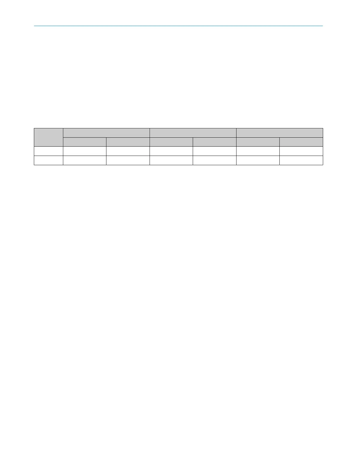
Table 2: Adjustable ranges for dynamic protective field widths
Resolution Small range Medium range Large range
Minimum
1)
Typical
2)
Minimum
1)
Typical
2)
Minimum
1)
Typical
2)
14 mm 0.15 m ... 4 m 0.15 m ... 5 m 1 m ... 8 m 1 m ... 10 m 2 m ... 16 m 2 m ... 20 m
30 mm 0 m ... 6 m 0 m ... 7.5 m 0 m ... 12 m 0 m ... 15 m 0 m ... 24 m 0 m ... 30 m
1)
The minimum scanning range specifies a range in which a function is guaranteed to operate correctly and safely under industrial
condit
ions. A sufficient level of signal reserve to ensure very high availability is included in the calculation.
2)
The typical scanning range specifies a range in which the safety light curtain operates correctly and safely under industrial conditions. The
level of signal reserve is enough to ensure high availability.
Further topics
•
"Minimum dis
tance to reflective surfaces", page 31
3.2.5 Beam coding.
Depending on its configuration, the safety light curtain operates with 1 of 3 beam
codin
gs: uncoded, code 1 or code 2. The beam coding “uncoded” allows for particularly
short response times. In order to avoid mutual interference between 2 neighboring
safety light curtains, one can be operated with code 1 and the other with code 2.
3.2.6 Reduced resolution
Using a reduced resolution, up to 2 adjacent beams can be interrupted without the
OSSDs switching to the OFF state.
As a result, smaller objects can move into the detection area of the safety light curtain
without the curtain reacting and the machine switching off. For this purpose, the permit‐
ted resolution is reduced by up to 2 beams.
The reduced resolution can be used for suppressing interference objects, if, for
instance, cables or hoses need to be routed through the protective field. The function
can be configured during commissioning.
3.2.7 Alignment aid
A laser alignment aid is installed in the sender of the safety light curtain. The laser
ali
gnment aid can be switched on to perform a simple alignment of the sender.
Diagnostic LEDs are installed in the receiver of the safety light curtain. For a simple
alignment of the receiver, diagnostic LEDs 1, 2, 3 and 4 indicate the alignment quality
once the safety light curtain has been switched on.
Diagnostic LEDs 5 and 6 light up if the topmost beam (far from system plug) is
synchronized. Diagnostic LEDs 7 and 8 light up if the bottommost beam (near system
plug) is synchronized.
3 P
RODUCT DESCRIPTION
14
O P E R A T I N G I N S T R U C T I O N S | deTec4 8021645/1EB0/2022-04-28 | SICK
Subject to change without notice