OFF
uncoded
code 1
code 2
rev.conf.
ON
1
O N
2
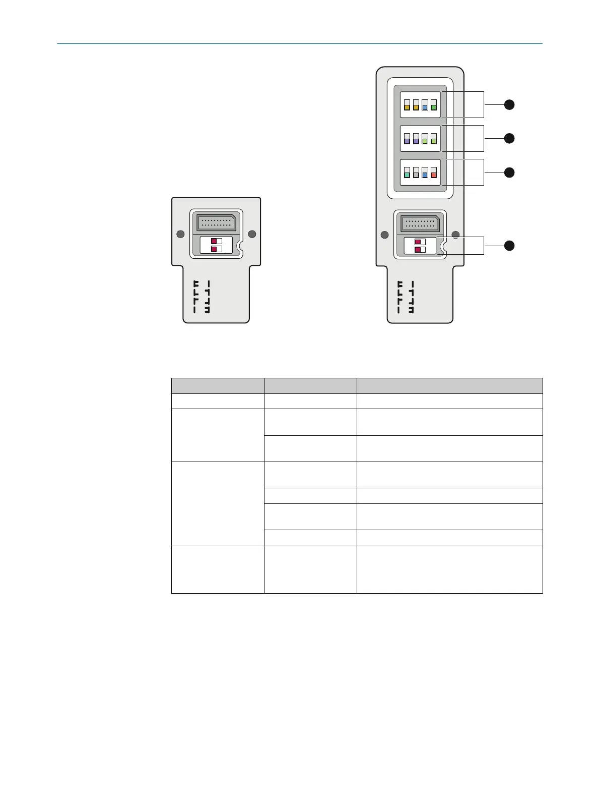
Figure 54: SP1 system plug with 2 DIP
s
witches
OFF
uncoded
code 1
code 2
rev.conf.
ON
1 2 3 4
O F F
1 2 3 4
O F F
1 2 3 4
O F F
1
O N
2
A
B
C
D
Figure 55: SP2 system plug with 14 DIP
s
witches
Table 29: Overview of DIP switches
Row DIP switch Function
A
1)
1, 2, 3, 4 Muting, see "C
onfiguring muting", page 97
B
1)
1, 2 Scanning range adjustment, see "Configuring
the scanning range", page 98
3, 4 Reduced resolution, see "C
onfiguring reduced
resolution", page 99
C
1)
1 Smart presence detection, see "Configuring
smart presence detection", page 100
2 Not assigned
3 Smart Box Detection
2)
, see "C
onfiguring Smart
Box Detection", page 101
4 Parity, see "Checking the parity", page 102
D 1, 2
•
Be
am coding, see "Configuring beam cod‐
ing", page 96
•
Reset to factory settings, see "Reset to fac‐
tory settings", page 94
1)
Only applies to SP2 system plug.
2)
On devices with range of functions 1.0.0, DIP switch 3 is not assigned.
Configuration information
b
Chec
k the parity using the SP2 system plug after setting the DIP switches. The
sum of the DIP switches of rows A, B and C set to On must be even. In case of an
uneven sum, change the setting of DIP switch 4 (row C).
b
Securely close the protective cover for the DIP switches, which is attached to the
SP2 system plug.
b
Then ensure the correct functioning of the device.
7 C
ONFIGURATION
92
O P E R A T I N G I N S T R U C T I O N S | deTec4 8021645/1EB0/2022-04-28 | SICK
Subject to change without notice