15.6.3 Change in scanning range using deflector mirrors
Important information
NOTE
T
he use of deflector mirrors reduces the scanning range depending on the number of
deflector mirrors in the protective field.
Table 86: Scanning range with and without 1 or 2 deflector mirrors
Type Solution Scanning
range, typi‐
cal
Scanning range with
1 deflector mirror, typi‐
cal
Scanning range with
2 deflector mirrors, typi‐
cal
PNS75, PNS125 14 mm 20 m D1 + D2 ≤ 18 m D1 + D2 + D3 ≤ 16.2 m
PNS75, PNS125 30 mm 30 m D1 + D2 ≤ 27 m D1 + D2 + D3 ≤ 24.3 m
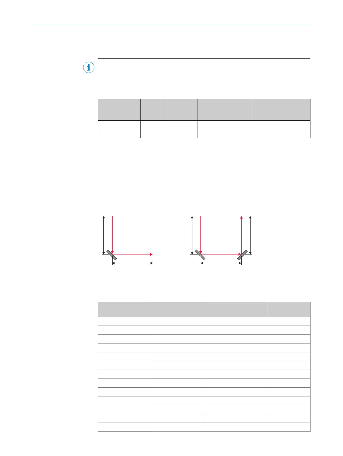
Example: Recommended distance when using deflector mirrors
This example assumes a 90° beam deflection per mirror, and a protective field height
of 900 mm.
When using a PNS75 deflector mirror, a distance of D
1
, D
2
, D
3
≤ 4 m between the
deflector mirror and the device, or between 2 mirrors is recommended.
When using a PNS125 deflector mirror, a distance of D
1
, D
2
, D
3
≤ 8 m between the
deflector mirror and the device, or between 2 mirrors is recommended.
Figure 75: Recommended distance when using deflector mirrors
15.6.4 Deflector mirror PNS75 - ordering information
Table 87: Ordering information for PNS75 deflector mirror
Mirror length in mm Max. protective field
hei
ght in mm
Type code Part number
340 300 PNS75-034 1019414
490 450 PNS75-049 1019415
640 600 PNS75-064 1019416
790 750 PNS75-079 1019417
940 900 PNS75-094 1019418
1090 1050 PNS75-109 1019419
1240 1200 PNS75-124 1019420
1390 1350 PNS75-139 1019421
1540 1500 PNS75-154 1019422
1690 1650 PNS75-169 1019423
1840 1800 PNS75-184 1019424
1990 1950 PNS75-199 1092962
2140 2100 PNS75-214 1092963
ACCESSORIES 15
8021645/1EB0/2022-04-28 | SICK O P E R A T I N G I N S T R U C T I O N S | deTec4
161
Subject to change without notice