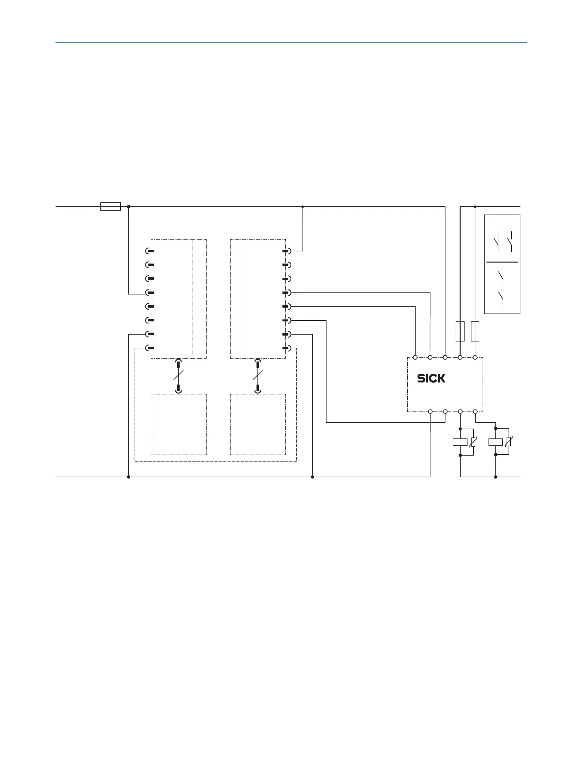
and released). The outputs (contacts 13-14 and 23-24) switch the K1 and K2
cont
actors on. When the protective field is interrupted, the OSSD 1 and OSSD 2
outputs switch the RLY3-OSSD2 off. Contactors K1 and K2 are switched off.
•
F
ault analysis
Cross-circuits and short-circuits of the OSSD 1 and OSSD 2 outputs are recognized
and le
ad to the locking state (lock-out). A malfunction with one of the K1 or K2
contactors is detected. The shut-down function is retained. In the event of manipu‐
lation (e.g., jamming) of the S1 pushbutton, the RLY3-OSSD2 will not re-enable the
output current circuits.
Cascade, 8-pin host, 5-pin guest, RLY3-OSSD1 safety relay
4) PELV
F2 F1
+24 V DC
0 V DC
K1K2
E324615/00/2021-09-29
k2
z
k1 k2
k1
z
x
y
x
1)
y
32
31I1 I2
24A2 14
23 13
RLY3-OSSD1
System connection
System connection
+24 V DC
deTec4 SP1
2
1
3
5
6
4
7
8
r
RES
ADO
OSSD 1
OSSD 2
EDM
0 V DC
MFP 1
s
+24 V DC
n.c
In 2
In 1
n.c
.
0 V DC
MFP 1
n.c.
2
3
4
5
6
1
7
8
2)
3)
F0
L+
L–
Figure 40: Connection diagram: Cascade, 8-pin host, 5-pin guest, RLY3-OSSD1
1) Output circuits. These contacts must be incorporated into the control such that the
d
angerous state is brought to an end if the output circuit is open. For categories 4 and
3, they must be incorporated on two channels (x, y paths). Single-channel incorporation
into the control (z path) is only possible with a single-channel control and taking the risk
analysis into account.
2) Connection of the 5-pin extension connection of the host device to the 5-pin system
connection of the guest device.
3) To indicate the status on both sides, the MFP 1 connections from the sender and receiver
must be connected to each other in the control cabinet (optional).
4) SELV/PELV safety extra-low voltage.
•
T
ask
Connection of two deTec4 safety light curtains to a RLY3-OSSD1 safety relay.
Oper
ating mode: Without restart interlock, with external device monitoring (EDM).
If required, the restart interlock is implemented via the machine controller.
•
Mode of oper
ation
4 P
ROJECT PLANNING
68
O P E R A T I N G I N S T R U C T I O N S | deTec4 8021645/1EB0/2022-04-28 | SICK
Subject to change without notice