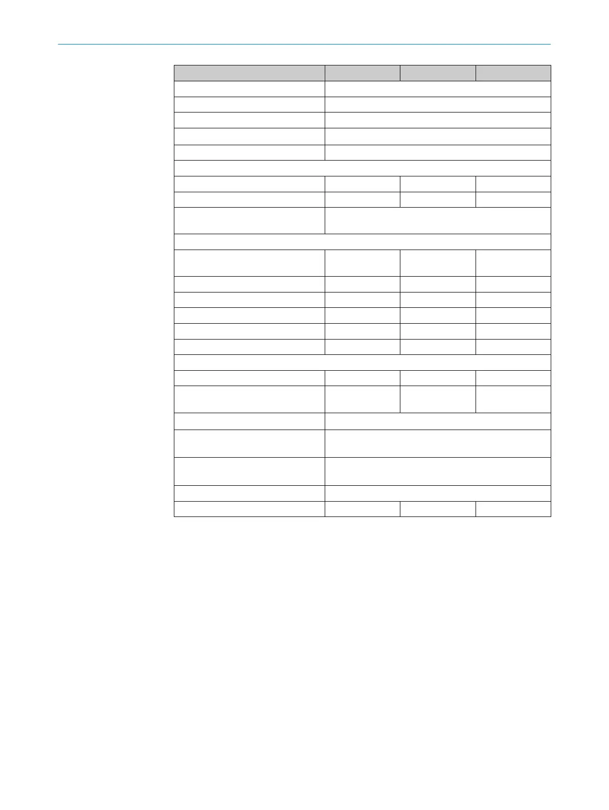
Minimum Typical Maximum
Single system 1,53 x 10
-8
Cascade with one guest 3,05 x 10
-8
Cascade with two guest devices 4,56 x 10
-8
T
M
(mis
sion time) 20 years (ISO 13849-1)
Safe status when a fault occurs At least one OSSD is in the OFF state.
Number of beams in a cascade
12)
13)
Beam coding uncoded No limit
Beam coding: code 1 or code 2 375 beams
Test rod speed at which the test rod
is r
eliably detected
14)
0 m/s … 1.6 m/s
Time monitoring for muting
Sensor gap monitoring (muting sen‐
sor and ESPE)
0.5 s
Muting end delay 0.2 s
Total time end of muting by ESPE
15)
0.7 s
Muting hold time 4 s
Concurrence monitoring 24 h
Total muting time 24 h
Smart Box Detection
Object speed 0.1 m/s 1 m/s
Object height h
bo
x
134 mm (Protective field
height - 54) mm
Object width w
box
min. 10 mm ... 100 mm
16)
Upper and lower object edge toler‐
anc
e dY
box
(object height)
min. 10 mm
Lateral object edge tolerance dX
bo
x
(object width)
17)
min. 6 mm ... 60 mm (uncoded system)
min. 4 mm ... 40 mm (coded system)
Minimum distance from objects min. 10 mm ... 100 mm
16)
Total Smart Box Detection time 24 h
1)
If the protective fields are very wide, there is a possibility that all four diagnostic LEDs 1, 2, 3 and 4 will
no
t light up even when alignment is optimal.
2)
The minimum scanning range specifies a range in which a function is guaranteed to operate correctly
and safely under industrial conditions. A sufficient level of signal reserve to ensure very high availability is
included in the calculation.
3)
The typical scanning range specifies a range in which the safety light curtain operates correctly and safely
under industrial conditions. The level of signal reserve is enough to ensure high availability.
4)
SELV/PELV safety extra-low voltage.
5)
The specified enclosure rating only applies if the system plug is fitted and the protective cover for the DIP
switches, which is attached to the SP2 system plug, is securely closed.
6)
The external voltage supply must be capable of bridging a brief power failure of 20 ms as specified in
IEC 60204-1. Suitable power supply units are available as accessories from SICK.
7)
A fuse rated maximum 2 A shall be installed in the 24 V DC power supply circuit to the device in order to
limit the available current.
8)
All inputs of the safety light curtain must be supplied by the same voltage supply. If the sender and
receiver are connected to each other, they must be supplied by the same voltage supply.
9)
Within the limits of U
V
.
10)
For more detailed information on the exact configuration of your machine, please contact your relevant
SIC
K subsidiary.
11)
The values apply for an installation height of up to 2,000 m above sea level. Additional information can
be found at your SICK subsidiary.
12)
The maximum permissible current must be observed.
13)
Calculation of number of beams:
TECHNICAL DATA 13
8021645/1EB0/2022-04-28 | SICK O P E R A T I N G I N S T R U C T I O N S | deTec4
141
Subject to change without notice