Receiver displays
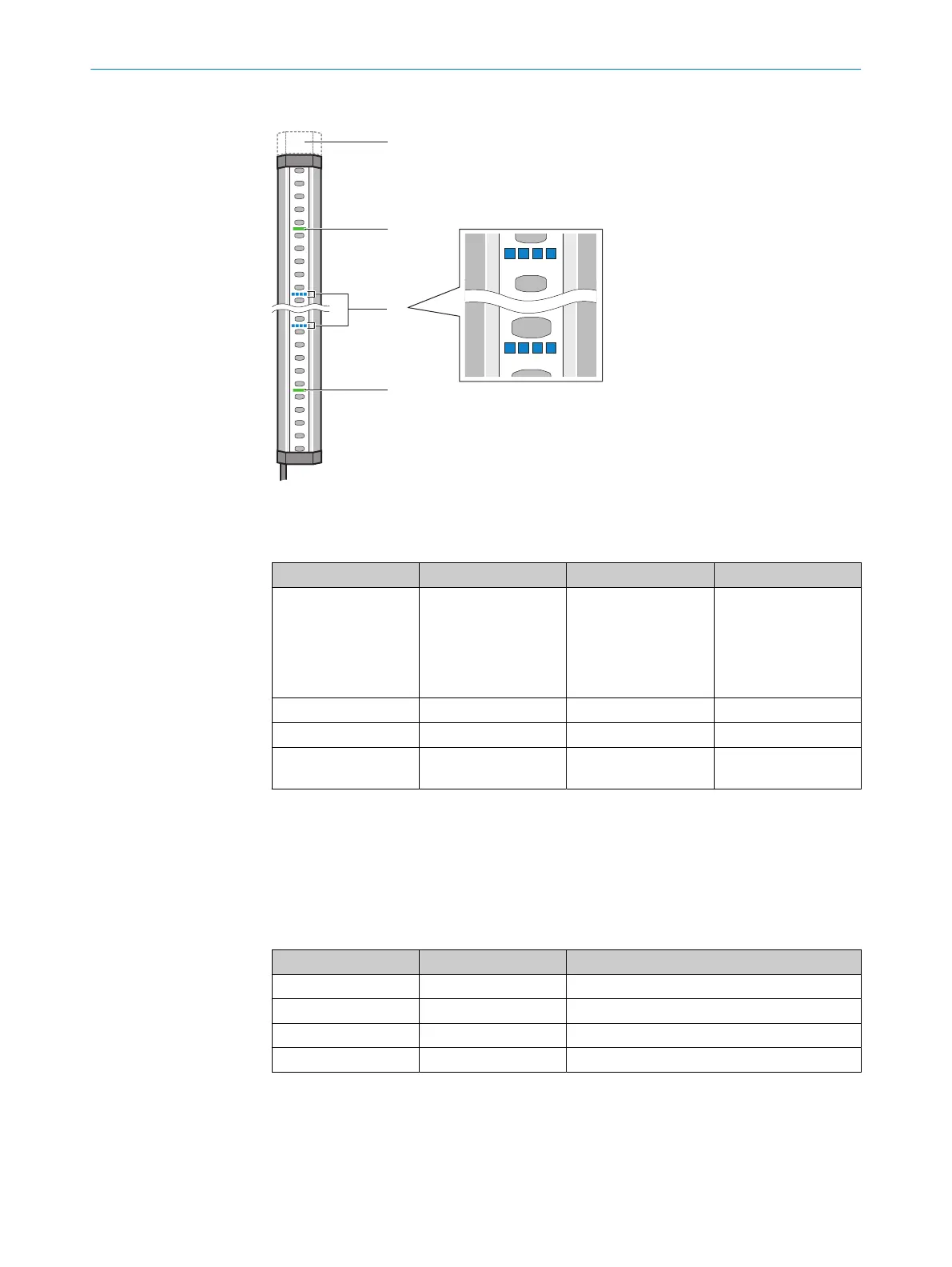
Figure 6: Receiver indicators
A
t least ten light emitting diodes on the receiver indicate the operational status:
Position LED color Function Labeling
!
Red/yellow/green Field indicator
1)
;
sho
ws the status of
the protective field
and additional infor‐
mation about the sta‐
tus display
–
"
Blue/red/yellow/white Diagnostics 1, 2, 3, 4, 5, 6, 7, 8
§
Red/green OSSD status OSSD
$
Red/yellow/green End cap with inte‐
g
rated LED (optional)
–
1)
Safety light curtains with protective field height > 300 mm have multiple LEDs for the field indicator.
Further topics
•
"Dia
gnostic LEDs", page 124
3.2.20.1 Indication of diagnostic LEDs
Table 7: Colors and their meaning
Color Color Meaning
O
White Configuration status
O
Blue Alignment quality
O
Red Fault indicator
O
Yellow Warning
o LED of
f. Ö LED flashes. O LED illuminates.
3 P
RODUCT DESCRIPTION
22
O P E R A T I N G I N S T R U C T I O N S | deTec4 8021645/1EB0/2022-04-28 | SICK
Subject to change without notice