Minimum Typical Maximum
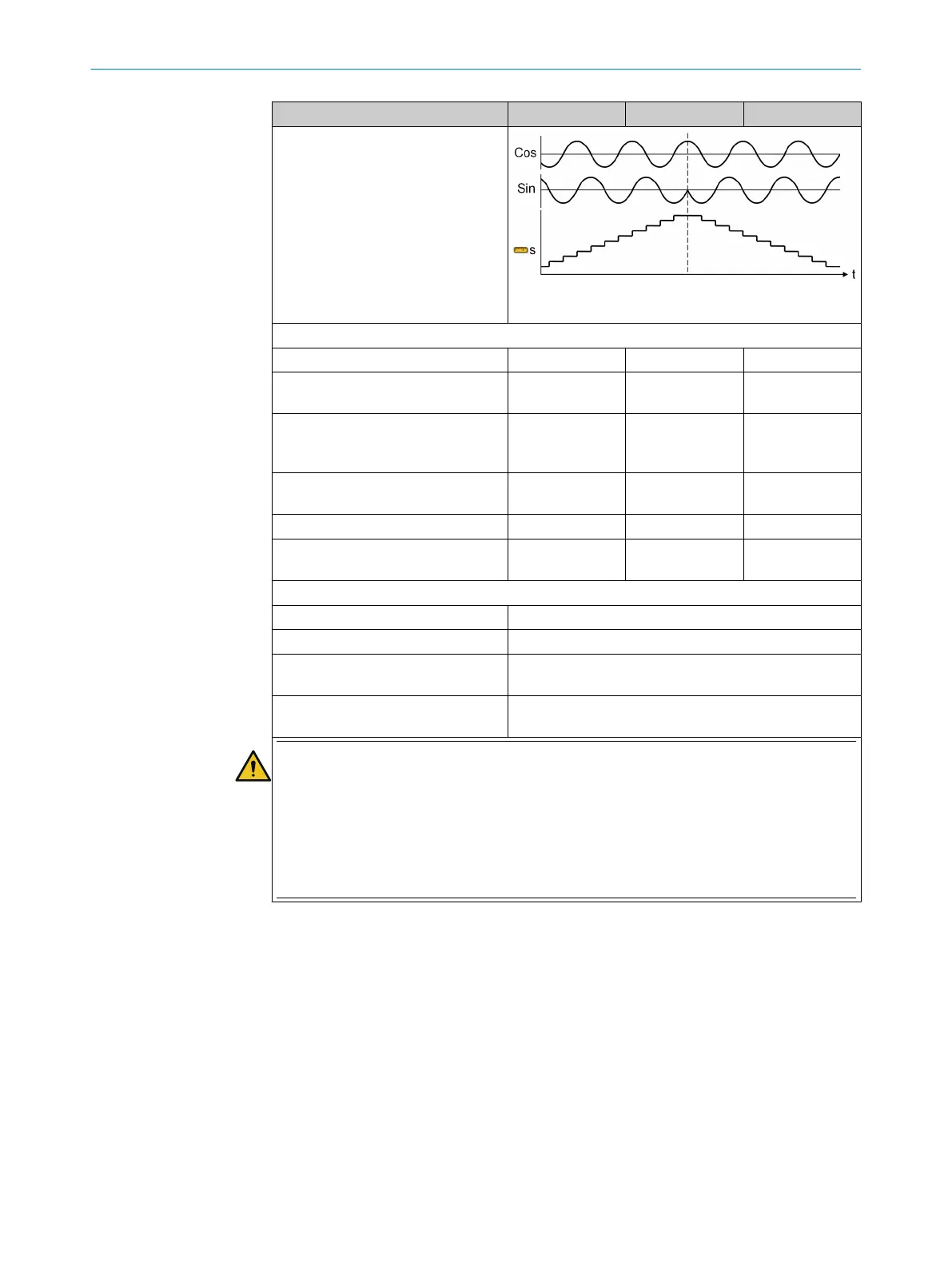
Counting direction
S = position information
SSI encoder (ENCx_A+, ENCx_A–, ENCx_C+, ENCx_C–, ENC_0V)
Baud rate
11
14
100kHz – 1MHz
Clock gap between data packages
(mono f
lop time)
12
100µs – –
Synchronization SSI Clock for SSI
ma
ster between encoder1 and
encoder2
–1ms – 1ms
“Max. data reception interval”
parameter tolerance
14
–0.5ms – 0.5ms
Number of position data bits
14
13
22
8 – 32
Number of bits of the complete SSI
protocol frame
14
13
23
8 – 62
Changing the position information (speed) per max. data reception interval
14
24
≤16 position data bits
14
Max. ½ value range of position data bits – 1 increment
≥17 position data bits
14
Max. 65,535 increments
Accuracy error affecting speed detec‐
t
ion
15
Max. 5% incl. the internal resolution of the speed infor‐
mation
Accuracy error affecting position
detection
16
Max. 1 increment of the internal resolution of the posi‐
tion information
WARNING
Incorrect data is output if the maximum speed is exceeded
The dangerous state may not be stopped or not be stopped in a timely manner in the event of
non-compliance.
The target safety-related level may not be achieved in the event of non-compliance.
►
Observe maximum speed.
►
Only use suitable encoders for the application.
1
Resistance between ENCx_y+/– and ENC_0V.
2
Resistance between ENCx_y+/– and ENC_0V. An input voltage of 30V between ENCx_y+/– and ENC_0V
w
ill not damage the module, e.g., in the event of voltage limiting, if the voltage exceeds 5V.
3
Resistance between between ENCx_y+ and ENCx_y– with series capacitor to block direct current load. An
input voltage of 30 V will not damage the module.
4
Voltage between A1 of the main module and ENCx_24V at 0.2A sum load current.
6
Voltage between ENCx_y+ and ENCx_y–.
7
Voltage between ENCx_y+ and ENC_0V as well as between ENCx_y– and ENC_0V.
8
Voltage between ENCx_y+ and ENCx_y– with a terminator of ≥60Ω.
9
Plus the resolution of the speed information based on the resolution of the encoder system:
a) Rotational movement in rpm = 15,000/(4 × number of A/B periods per revolution)
b) Linear movement in mm/s = 250/(4 × number of A/B periods per revolution)
10
Plus the resolution of the position information based on the resolution of the encoder system:
1rev./(4 × number of A/B periods per revolution).
11
Master and listener mode.
12
Time between the falling edges of the clock.
13
Without start bit. If repeat transmission is used (clock continues without clock gap so that the same data
can be transmitted again), the entire stream is viewed as a frame.
12 T
ECHNICAL DATA
158
O P E R A T I N G I N S T R U C T I O N S | Flexi Soft Modular Safety Controller 8012478/1IG6/2023-02-24 | SICK
Subject to change without notice