5.2.7 FX0-STIO I/O module
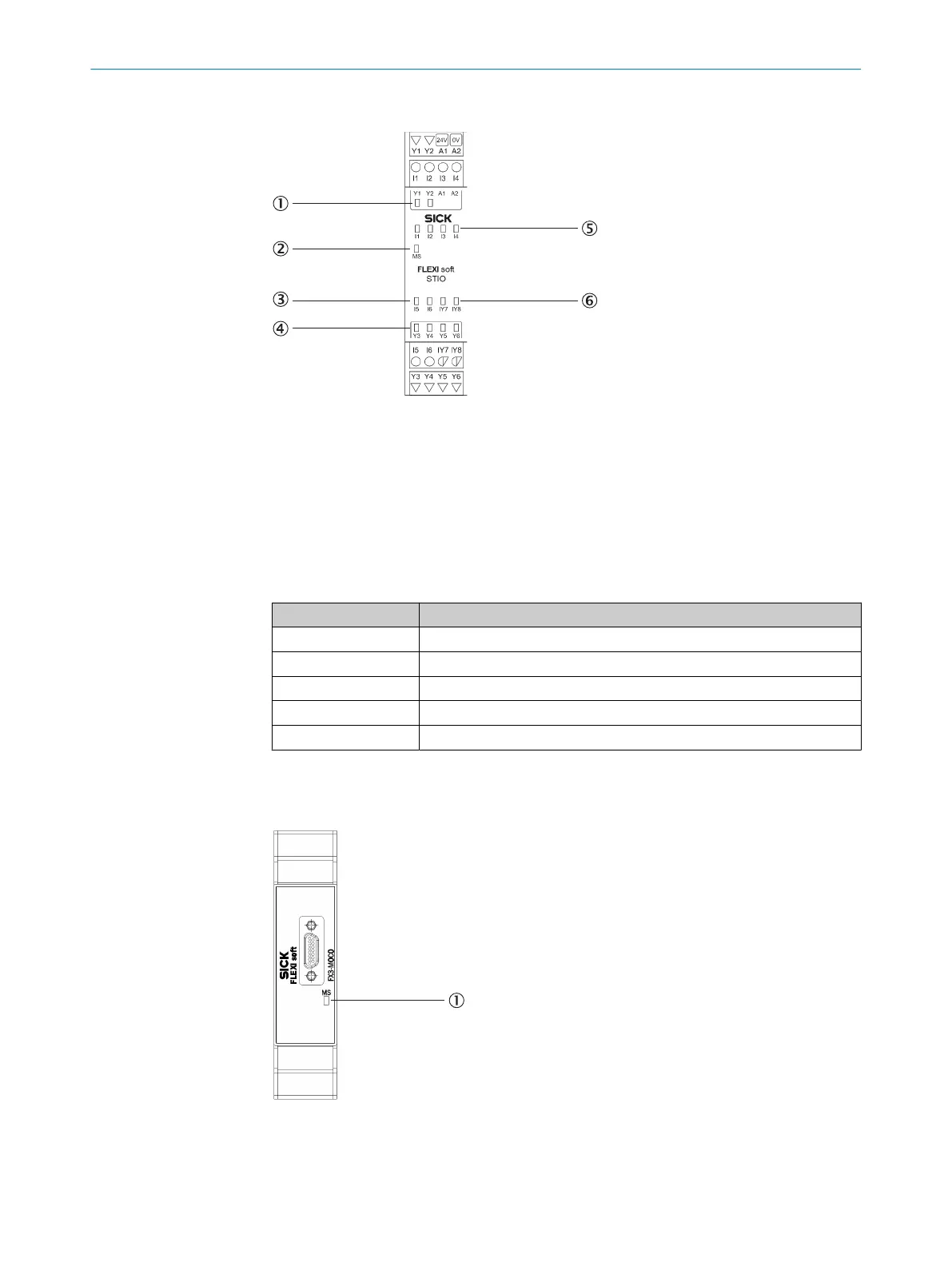
Figure 34: FX0-STIO I/O module
1
2 output LEDs
2
MS LED (Module St
atus)
3
2 input LEDs
4
4 output LEDs
5
4 input LEDs
6
2 LEDs for configurable inputs or outputs
Table 24: Pin assignment for the FX0-STIO I/O module
Terminal Pin assignment
A1 24 V
A2 GND
I1 … I6 Non-safe inputs 1 to 6
IY7, IY8 Non-safe inputs 7 and 8 or non-safe outputs 7 and 8 (configurable)
Y1 … Y6 Non-safe outputs 1 to 6
5.2.8 FX3-MOCx motion control module
Overview
Figure 35: FX3-MOCx motion control module
1
MS LED (Module Status)
ELECTRICAL INSTALLATION 5
8012478/1IG6/2023-02-24 | SICK O P E R A T I N G I N S T R U C T I O N S | Flexi Soft Modular Safety Controller
59
Subject to change without notice