5.2.6 FX3-XTDS I/O module
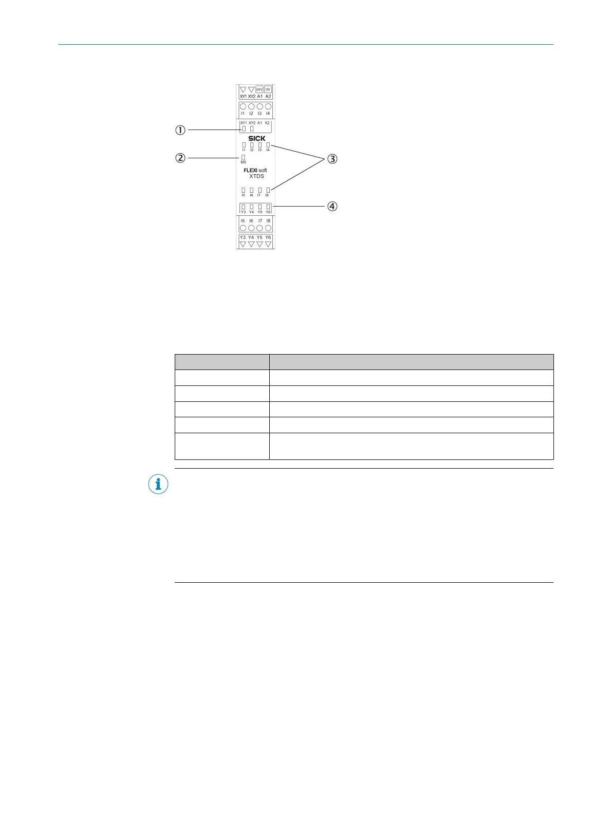
Figure 33: FX3-XTDS I/O module
1
2 LEDs for test outputs or non-safe outputs
2
MS LED (Module St
atus)
3
8 input LEDs
4
4 output LEDs
Table 23: Pin assignment for the FX3-XTDS I/O module
Terminal Pin assignment
A1 24 V
A2 GND
I1 … I8 Safety inputs 1 to 8
Y3 … Y6 Non-safe outputs 3 to 6
XY1/XY2 Test output 1/Test output 2 or
non-
safe output 1/non-safe output 2
NOTE
Use of t
hetest outputs
The FX3-XTDShas two optional test outputs.
•
For each device to be tested, one test output must be used of the same module to
which the device is connected.
•
If the device to be tested is connected to an odd-numbered input (I1, I3, I5, I7),
then test output XY1 mustbe used. If the device to be tested is connected to an
even-numbered input (I2, I4, I6, I8), then test output XY2 mustbe used.
5 ELE
CTRICAL INSTALLATION
58
O P E R A T I N G I N S T R U C T I O N S | Flexi Soft Modular Safety Controller 8012478/1IG6/2023-02-24 | SICK
Subject to change without notice