FX3-CPU3 main module
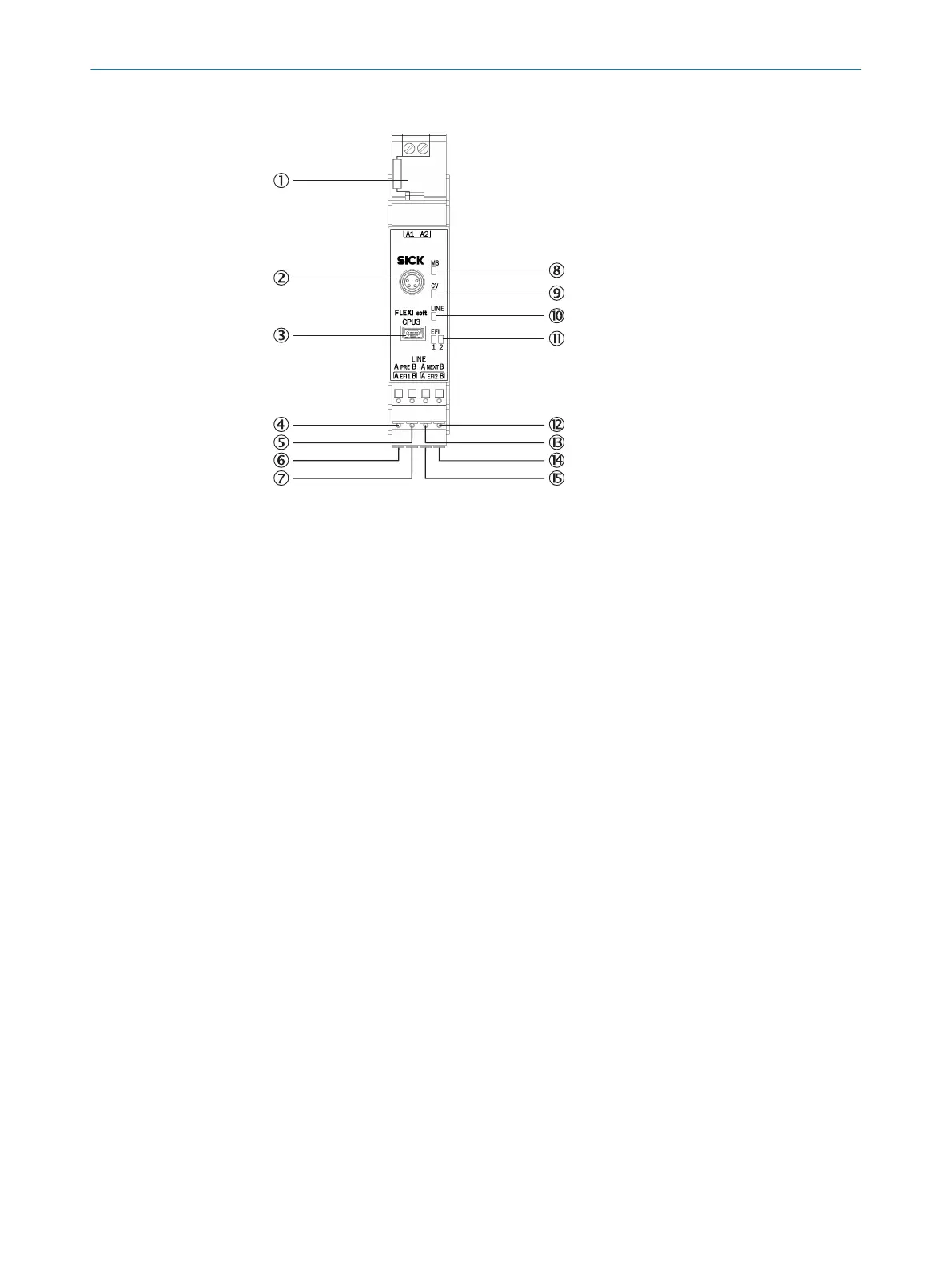
Figure 6: FX3-CPU3 main module
1
FX3-MPL1 system plug
2
RS-232 interface
3
USB interface
4
Line_PRE_A (previous)
5
Line_PRE_B (previous)
6
EFI1_A
7
EFI1_B
8
MS LED (Module St
atus)
9
CV LED (Configuration Verified)
ß
LINE LED
à
EFI1 and EFI2 LEDs
á
Line_NEXT_B (next)
â
Line_NEXT_A (next)
ã
EFI2_B
ä
EFI2_A
Further topics
•
"F
lexi Line", page 46
•
"USB", page 43
3.4.5 FX3-MPL0 and FX3-MPL1 system plugs
Overview
T
here is a system plug at each main module. The system configuration for the entire
Flexi Soft system is stored only in the system plug. This is beneficial when replacing
modules, because it means that a full reconfiguration of the Flexi Soft system is not
required.
PRODUCT DESCRIPTION 3
8012478/1IG6/2023-02-24 | SICK O P E R A T I N G I N S T R U C T I O N S | Flexi Soft Modular Safety Controller
23
Subject to change without notice