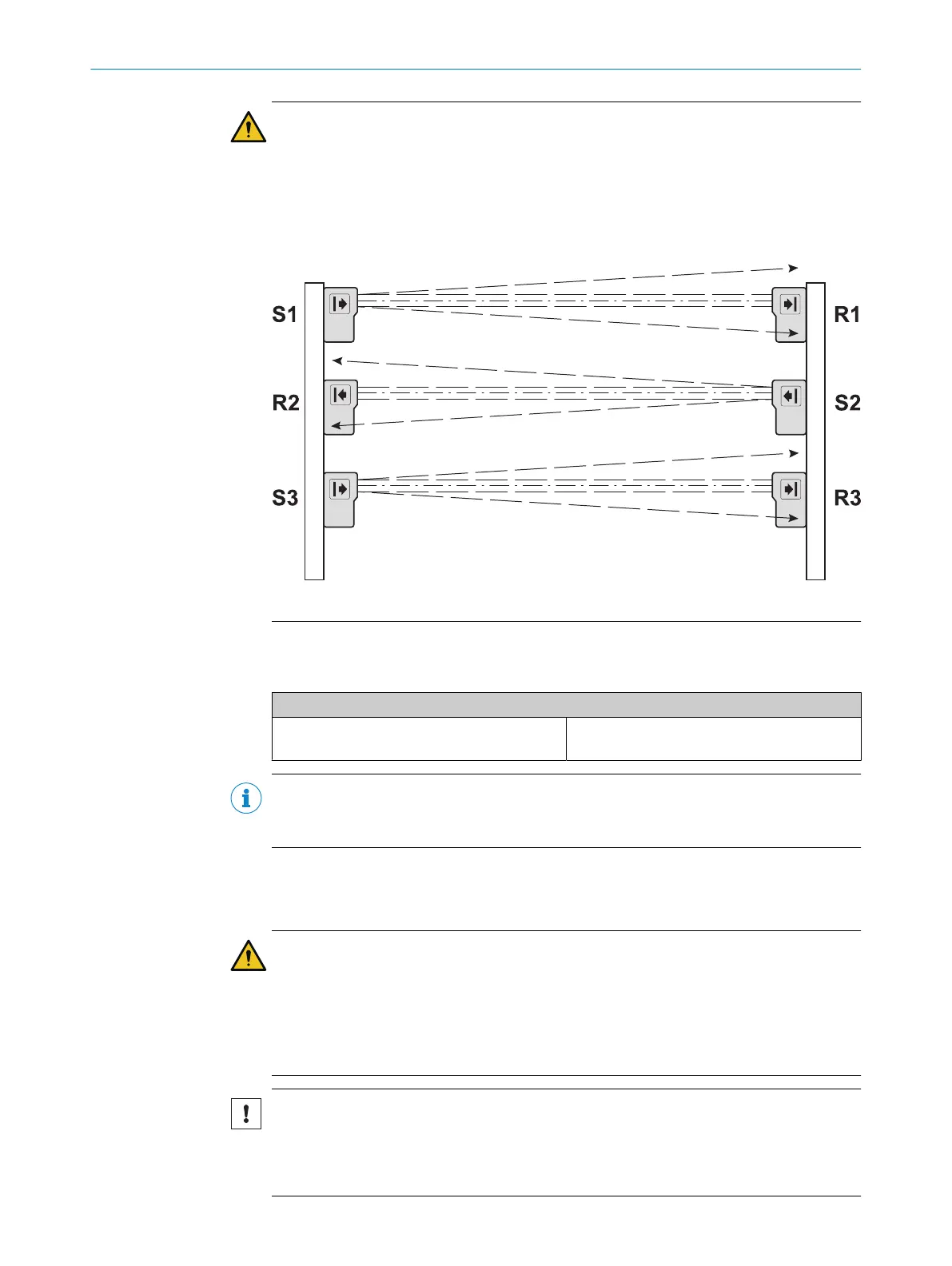
WARNING
Ine
ffectiveness of the protective device due to mutual optical interference
If several safety single-beam sensors pairs are used:
►
Observe the aperture angle of the sensors to exclude mutual optical interference.
►
Ensure that the light beam from each sender only reaches the associated
receiver.To do so, mutual mounting (among other things) of the sender and
receiver can be required between the sender and receiver.
Figure 53: Mutual mounting to avoid mutual optical interference
5.4.4 Electro-sensitive protective devices
Table 76: Connection of electro-sensitive protective devices
Electrical connection: example with FX3-XTIO
C2000, C4000, M2000, M4000, S300,
S3000, V300, mini
Twin
OSSD1 (receiver) at I1
OSSD2 (receiver) at I2
NOTE
Y
ou will find more information in the operating instructions for the corresponding elec‐
tro-sensitive protective devices.
5.4.5 Safety outputs Q1 to Q4
Important information
WARNING
Ine
ffectiveness of the protective device due to unintended switching of actuators
The dangerous state may not be stopped or not be stopped in a timely manner in the
event of non-compliance.
►
Connect the GND connections of the actuators to the outputs Q1 to Q4 in star
formation with the GND connection of the voltage supply.
NOTICE
Ex
ceeding the nominal values at the outputs
The device may be damaged if this is not observed.
►
Do not connect any loads that exceed the nominal values of the outputs Q1 to Q4.
ELECTRICAL INSTALLATION 5
8012478/1IG6/2023-02-24 | SICK O P E R A T I N G I N S T R U C T I O N S | Flexi Soft Modular Safety Controller
89
Subject to change without notice