Instead of two redundant sensors, an individual single-channel or dual-channel safety
sensor c
an be used. A single-channel safety sensor must be connected in series to
both inputs.
Further topics
•
"C
onstruction and function", page 17
•
"Connecting analog sensors", page 96
3.4.13 UE410-2RO/UE410-4RO relay modules
Overview
T
he UE410-2RO/UE410-4RO relay modules provide dual-channel, contact-based out‐
puts with what are known as positively guided relay contacts.
Important information
NOTE
T
he relay modules do not participate in communication via the internal FLEXBUS+ bus.
Therefore, they cannot receive control signals from the main module.
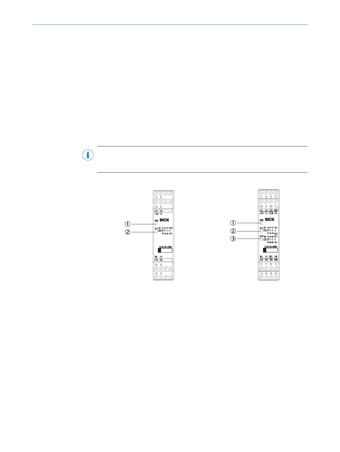
Relay modules UE410-2RO/UE410-4RO
Figure 21: Relay module UE410-2RO
1
PWR LED (power)
2
K1/2 LED
Figure 22: Relay module UE410-4RO
1
PWR LED (power)
2
K1/2 LED
3
K3/4 LED
Further topics
•
"C
onstruction and function", page 17
3.4.13.1 Internal circuitry
UE410-2RO
T
he UE410-2RO relay module has a control input (B1). This controls two internal relays
and provides a redundant cut-off path, consisting of:
•
Two safe enabling current paths (13/14, 23/24), dual-channel and volt-free
•
One signaling current path (Y14), dual-channel and connected internally to 24 V
DC
•
One feedback circuit external device monitoring (Y1/Y2), dual-channel and volt-
free
PRODUCT DESCRIPTION 3
8012478/1IG6/2023-02-24 | SICK O P E R A T I N G I N S T R U C T I O N S | Flexi Soft Modular Safety Controller
41
Subject to change without notice