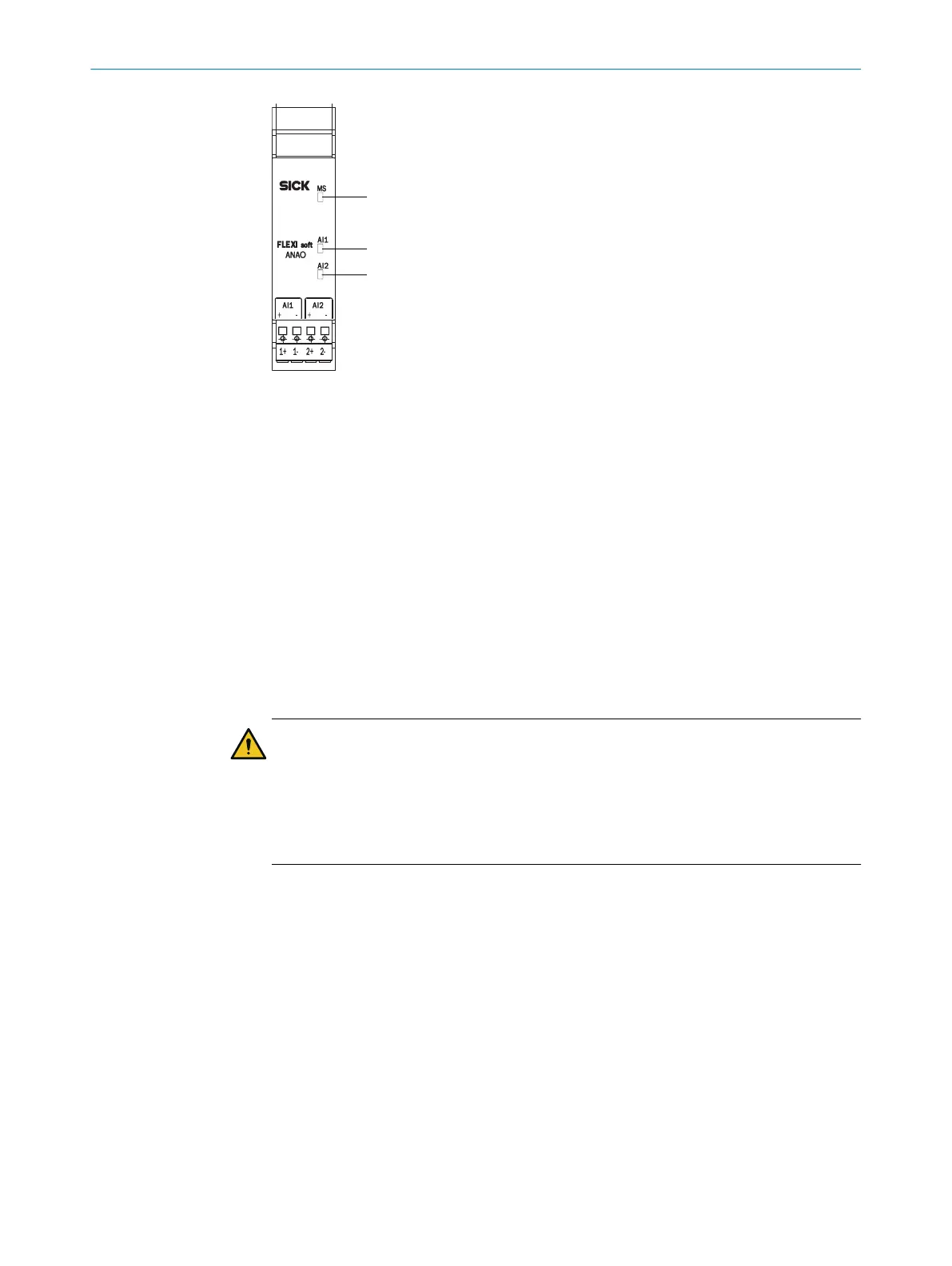
Figure 20: Analog input module FX3-ANA0
1
MS LED (module status)
2
LED AI1
3
LED AI2
Configuration
T
he FX3-ANA0 is configured using the Flexi Soft Designer or Safety Designer configura‐
tion software.
Devices with firmware <V2.00.0 are not supported by the Safety Designer configura‐
tion software.
For detailed information on configuring the FX3-ANA0, see the “FlexiSoft in the
FlexiSoft Designer Configuration Software” and “FlexiSoft in the Safety Designer
Configuration Software” operating instructions.
Sensors
WARNING
Ine
ffectiveness of the protective device due to selection of unsuitable sensors
The target safety-related level may not be achieved in the event of non-compliance.
►
Select suitable sensors.
►
Take suitable measures against the sensors’ systematic errors and common
causes of error.
Choosing the right sensors is crucial to achieving the desired safety integrity level
(SIL
) and performance level (PL). Systematic faults and common cause faults (CCF), in
particular, need to be minimized in this case.
Sensors featuring diverse redundancy are supported for the safe measurement of a
process variable. The characteristic lines of the sensors are standardized in the module
for this purpose. The standardized measured values of the two sensors are compared
with one another in order to check their plausibility.
Uniformly redundant sensors can also be used. In this case, the characteristic lines of
both sensors must have identical configurations.
Depending on the process variable, a time delay can occur at sensors which are
attached at a distance from one another within a local area, or which have different
transceivers. This transit time difference can be taken into account during the plausibil‐
ity check.
3 P
RODUCT DESCRIPTION
40
O P E R A T I N G I N S T R U C T I O N S | Flexi Soft Modular Safety Controller 8012478/1IG6/2023-02-24 | SICK
Subject to change without notice