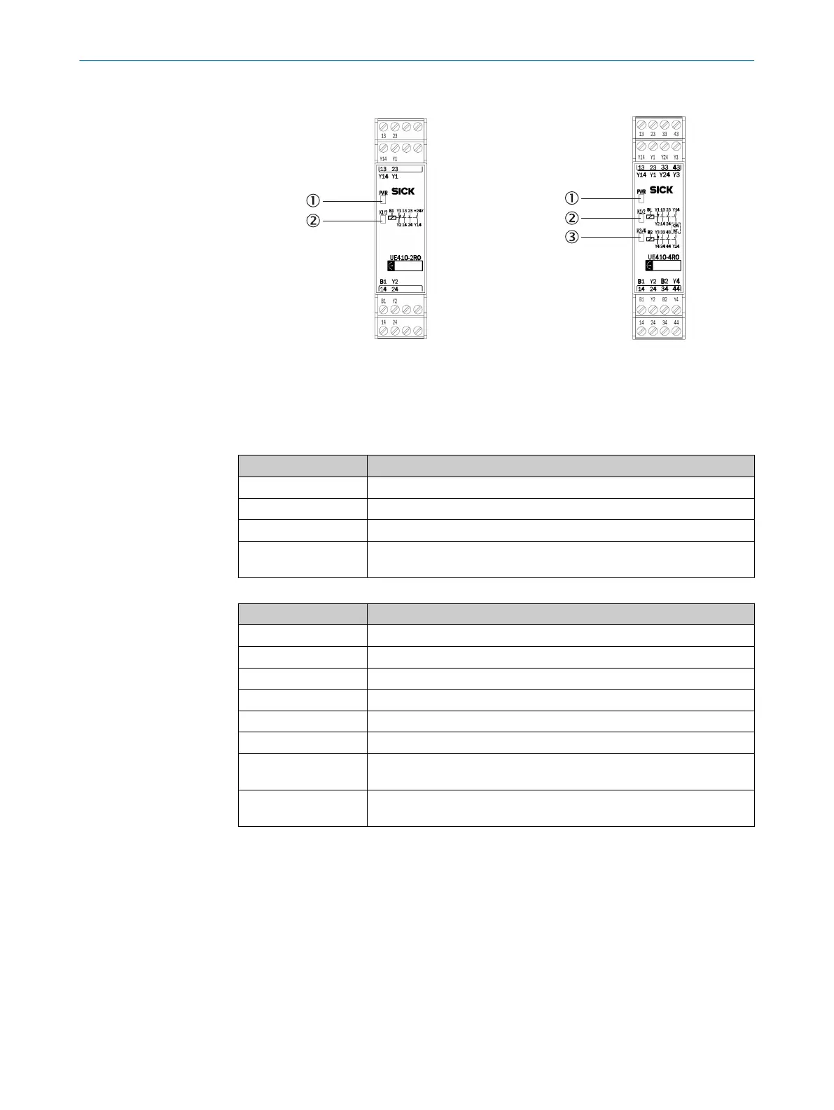
5.2.13 UE410-2RO and UE410-4RO relay modules
Figure 44: UE410-2RO relay module
1
PWR LED (power)
2
K1/2 LED
Figure 45: UE410-4RO relay module
1
PWR LED (power)
2
K1/2 LED
3
K3/4 LED
Table 47: Pin assignment for the UE410-2RO relay module
Terminal Pin assignment
B1 Wiring of relay K1/K2
13/14 and 23/24 Safety contacts for cutoff circuit K1/K2
Y1/Y2 Feedback circuit external device monitoring (EDM), normally closed
Y14
Safety contact K1/K2, current limited, normally open contact (see
"T
echnical data", page 130)
Table 48: Pin assignment for the UE410-4RO relay module
Terminal Pin assignment
B1 Wiring of relay K1/K2
B2 Wiring of relay K3/K4
13/14 and 23/24 Safety contacts for cut-off circuit outputs K1/K2
33/34 and 43/44 Safety contacts for cut-off circuit outputs K1/K2
Y1/Y2 Feedback circuit external device monitoring K1/K2, normally closed
Y3/Y4 Feedback circuit external device monitoring K3/K4, normally closed
Y14
Safety contact K1/K2, current limited, normally open contact (see
"T
echnical data", page 130)
Y24
Safety contact K3/K4, current limited, normally open contact (see
"T
echnical data", page 130)
The UE410-2RO/UE410-4RO relay modules cannot be used alone, but must be
s
witched via a module FX3-XTIO. To do so, a control output of the module FX3-XTIO
(Q1 to Q4) must be connected with a control input of the relay module (B1, B2).
In addition, the feedback contacts Y1/Y2 on UE410-2RO and the feedback contacts
Y1/Y2 and Y3/Y4 on relay module UE410-4RO must be connected with the FX3-XTIO.
ELECTRICAL INSTALLATION 5
8012478/1IG6/2023-02-24 | SICK O P E R A T I N G I N S T R U C T I O N S | Flexi Soft Modular Safety Controller
75
Subject to change without notice