Length of cable Cable type
Up to 125m 2 × 0.34mm² (AWG 22)
Up to 1,000m 2 × 0.75mm² (AWG 18)
•
SIC
K offers a suitable cable for connections up to 40m (SICK part number
6029448, 2 × 0.22mm², sold by the meter, see "Accessories for the safety
controller", page 182).
Further topics
•
"EMC me
asures for Flexi Link and Flexi Line", page 101
5.4.12 EMC measures for Flexi Link and Flexi Line
Flexi Link and Flexi Line cables are used for the transmission of communication signals.
E
lectromagnetic interference can disrupt signal transmission and interrupt communica‐
tion. The following measures are necessary to minimize electromagnetic interference:
►
Ensure sufficient equipotential bonding of the connection points for the shielding.
In doing so, follow the applicable standards and directives.
►
Connect all inactive metal parts (doors and housing of the control cabinet, DIN
mounting rails, etc.) to the ground potential.
►
Always connect the cable shielding to the ground connection across a large area
at both ends.
►
Use suitable cable clamps to connect the shielding of the shielded cables to
the ground potential directly at the access to the system (control cabinet, frame,
DIN mounting rail). The cable clamps must reach all the way around the cable
shielding.
►
Use suitable cable clamps to connect the cable shielding to the ground potential,
once again as close as possible to the main module (e.g. on the DIN mounting
rail). The cable clamps must reach all the way around the cable shielding.
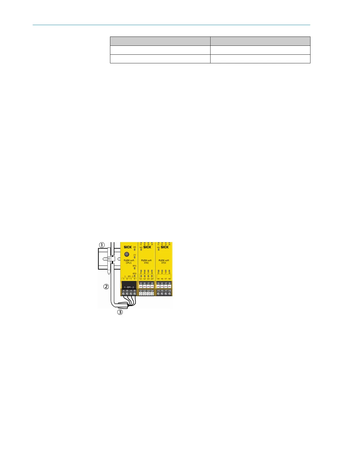
Figure 61: Connect the cable shielding to the DIN mounting rail
1
DIN mounting rail
2
Cable
3
Heat-shrinkable sleeve
►
K
eep the cable ends from which the insulation has been stripped as short as
possible.
►
Insulate the end of the shielding braid, for example using a suitable heat-shrinka‐
ble sleeve.
ELECTRICAL INSTALLATION 5
8012478/1IG6/2023-02-24 | SICK O P E R A T I N G I N S T R U C T I O N S | Flexi Soft Modular Safety Controller
101
Subject to change without notice