5.4.2.3 Transponders T4000 Compact and T4000 Direct
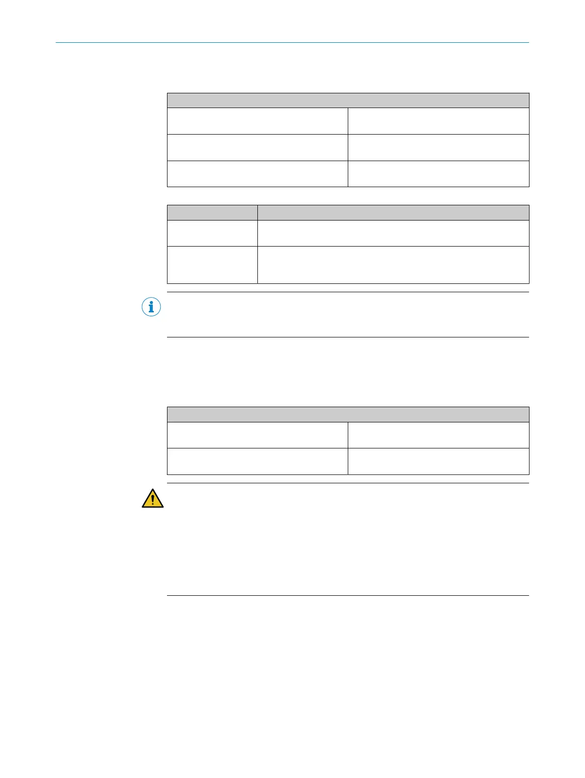
Table 70: Connection of the transponders
Electrical connection: example with FX3-XTIO
T4000 Compact (at 24 V) 24 V at +LA, I1 at LA
24 V a
t +LB, I2 at LB
T4000 Compact (at test output) X1 at +LA, I3 at LA
X2 a
t +LB, I4 at LB
T4000 Direct (with OSSD) 24 V at UB (T4000), I5 at OA
24 V a
t UB (T4000), I6 at OB
Table 71: Functions with transponders
Function Notes
Tested Possible for T4000 Compact
N
ot necessary for the T4000 Direct, as self-monitoring
Series connec‐
t
ion/cascading
T4000 Compact cannot be cascaded
T4000 Direct: Please note the maximum conductor resistance of 100
Ω (see "Technical data", page 130).
NOTE
Y
ou will find more information in the operating instructions for the T4000 Compact and
T4000 Direct transponders.
5.4.3 Testable safety single-beam sensors
5.4.3.1 Testable type 2 safety single-beam sensors
Table 72: Connection of testable type 2 safety single-beam sensors
Electrical connection: example with FX3-XTIO
Wx12/24/27, Vx18 Test input TI (sender) at X1
Out
put Q (receiver) at I1
L21, L27/L28 Test input TI (sender) at X2
Out
put Q (receiver) at I2
WARNING
Im
pairment of fault detection due to cross-circuit
The dangerous state may not be stopped or not be stopped in a timely manner in the
event of non-compliance.
►
Prevent cross-circuits between the connection from the test output of the Flexi
Soft module to the test input of the sender and the connection from the output of
the receiver to the safe input of the Flexi Soft module with protected or separate
cabling.
ELECTRICAL INSTALLATION 5
8012478/1IG6/2023-02-24 | SICK O P E R A T I N G I N S T R U C T I O N S | Flexi Soft Modular Safety Controller
85
Subject to change without notice