3 Product description
3.1 System characteristics
Sensors and switching elements (e.g. light curtains, laser scanners, switches, sensors,
encoder
s, emergency stop pushbutton) are connected to the Flexi Soft modular safety
controller and are linked logically. The corresponding actuators of the machines or
systems can be switched off safely via the switching outputs of the safety controller.
The Flexi Soft system is distinguished by the following system characteristics:
•
Modular design: 1 main module, up to 2 different gateways, and up to 12 expan‐
sion modules
1)
•
Up to 96safe digital inputs
•
Up to 12safe analog inputs
2)
•
Up to 48safe digital outputs or up to 96non-safe digital outputs
•
Configurable
•
.Use of up to 255 logic and application-specific function blocks
•
Logic function blocks, including, e.g., AND, OR, NOT, XNOR, XOR
•
Application-specific function blocks including, e.g., emergency stop, two-hand,
muting, presses, ramp-down detection, operating mode selector switch, reset,
restart
•
Can be integrated into different networks with gateways (EtherNet/IP™, Modbus
TCP, PROFINET IO, PROFIBUS DP, DeviceNet, CANopen and EtherCAT)
•
Safe gateway for EFI-pro
•
2 EFI interfaces on FX3-CPU1, FX3-CPU2, and FX3-CPU3 main modules (see "FX3-
CPU1 main module", page 20)
The Flexi Soft Designer and Safety Designer configuration softwares are available for
configuration of the control tasks.
NOTE
T
he available range of performance of the Flexi Soft systems depends on the configura‐
tion software used, see "Version, compatibility, and features", page 14.
You will find the configuration software on the Internet: www
.sick.com
3.2 Version, compatibility, and features
There are different firmware versions and function packages (so-called “Steps”) for the
F
lexi Soft product family that permit realization of the different functions. This section
provides an overview of which firmware version, which function package and/or which
version of the Flexi Soft Designer configuration software orSafety Designerconfigura‐
tion software is needed to use a certain function or a certain device.
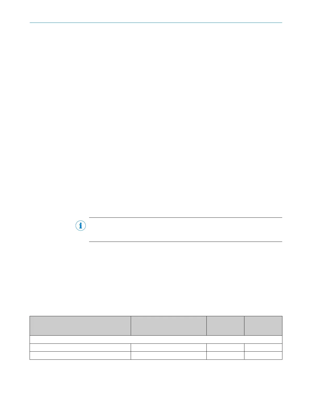
Table 3: Modules, firmware versions, and software versions you will need
Necessary module with firmware
fr
om version
Available from
Flexi Soft
Designer
Available from
Safety Designer
Function blocks and logic
Offline simulation of logic Unrestricted V1.2.0 V1.6.x
Import and export of partial applications Unrestricted V1.3.0 V1.6.x
1)
T
he number of expansion modules is limited by the capacity of the FLEXBUS+ backplane bus. A motion control module (FX3-MOCx)
requires twice the bus capacity of the other expansion modules. Therefore, each FX3-MOCx reduces the maximum possible number of
expansion modules that can be used by two.
2)
Each FX3-ANA0 expansion module provides two analog inputs, which are combined to form one safe channel.An FX3-ANA0 can
therefore safely detect an analog process variable using two sensors.
3 P
RODUCT DESCRIPTION
14
O P E R A T I N G I N S T R U C T I O N S | Flexi Soft Modular Safety Controller 8012478/1IG6/2023-02-24 | SICK
Subject to change without notice