WARNING
U
nintended high status at the inputs due to reverse current in case of loss of ground
connection
The target safety-related level may not be achieved in the event of non-compliance.
The dangerous state may not be stopped or not be stopped in a timely manner in the
event of non-compliance.
If several safety inputs are connected in parallel:
►
Check whether this reverse current might lead to an unintentional high state, see
"Technical data", page 130.
►
Consider this possible error source in the risk analysis and risk avoidance strategy.
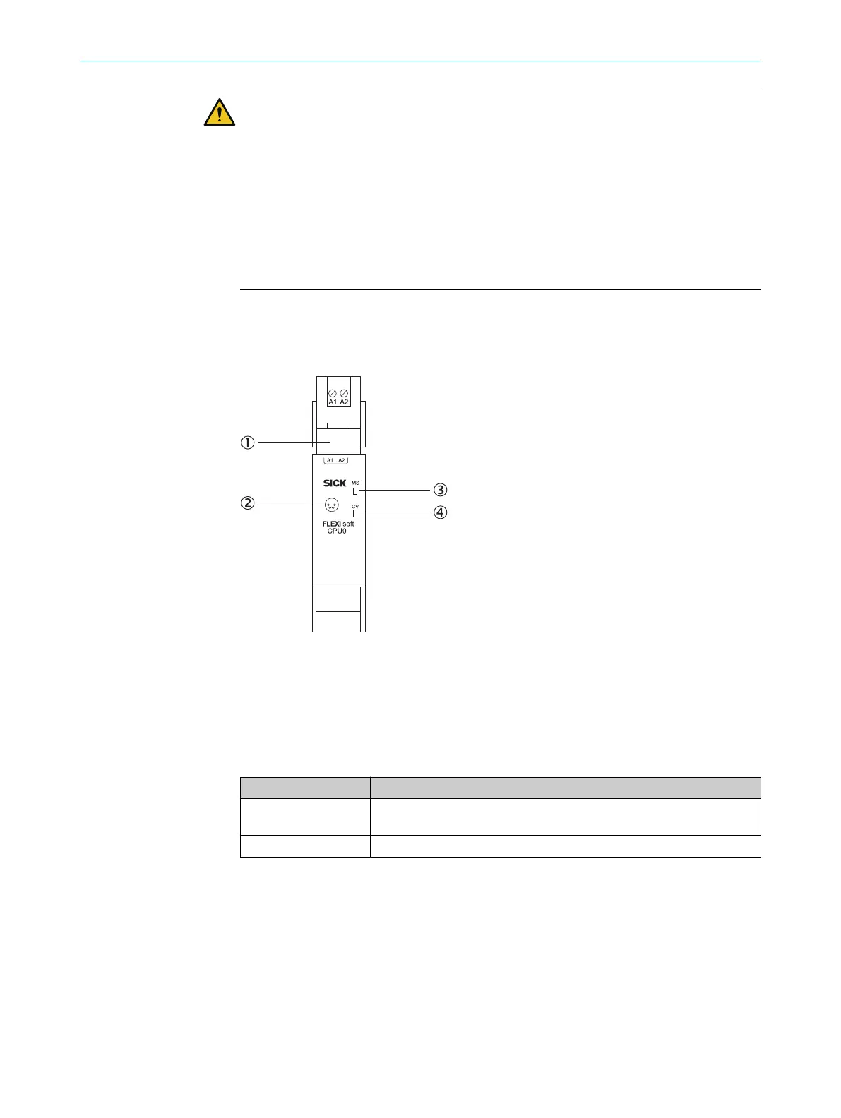
5.2 Description of the terminals
5.2.1 FX3-CPU0 main module
Figure 27: FX3-CPU0 main module
1
FX3-MPL0 system plug
2
RS-232 interface
3
MS LED (Module St
atus)
4
CV LED (Configuration Verified)
Table 18: Pin assignment on the FX3-CPU0 main module with FX3-MLP0 system plug
Terminal Pin assignment
A1 24 V power supply for all modules, with the exception of the supply to
t
he outputs (Q1 … Q4)
A2 Power supply GND
ELECTRICAL INSTALLATION 5
8012478/1IG6/2023-02-24 | SICK O P E R A T I N G I N S T R U C T I O N S | Flexi Soft Modular Safety Controller
53
Subject to change without notice