5
MS LED (Module St
atus)
6
CV LED (Configuration Verified)
7
EFI1 LED
8
EFI2 LED
9
EFI2_B
ß
EFI2_A
Table 19: Pin assignment at FX3-CPU1 main module with FX3-MPL0 system plug and at FX3-
CPU2 main module with FX3-MPL1 system plug
Terminal Pin assignment
A1 24 V power supply for all modules, with the exception of the supply to
t
he outputs (Q1 … Q4)
A2 Power supply GND
EFI1_A Connections for EFI or for Flexi Link
EFI1_B
EFI2_A
EFI2_B
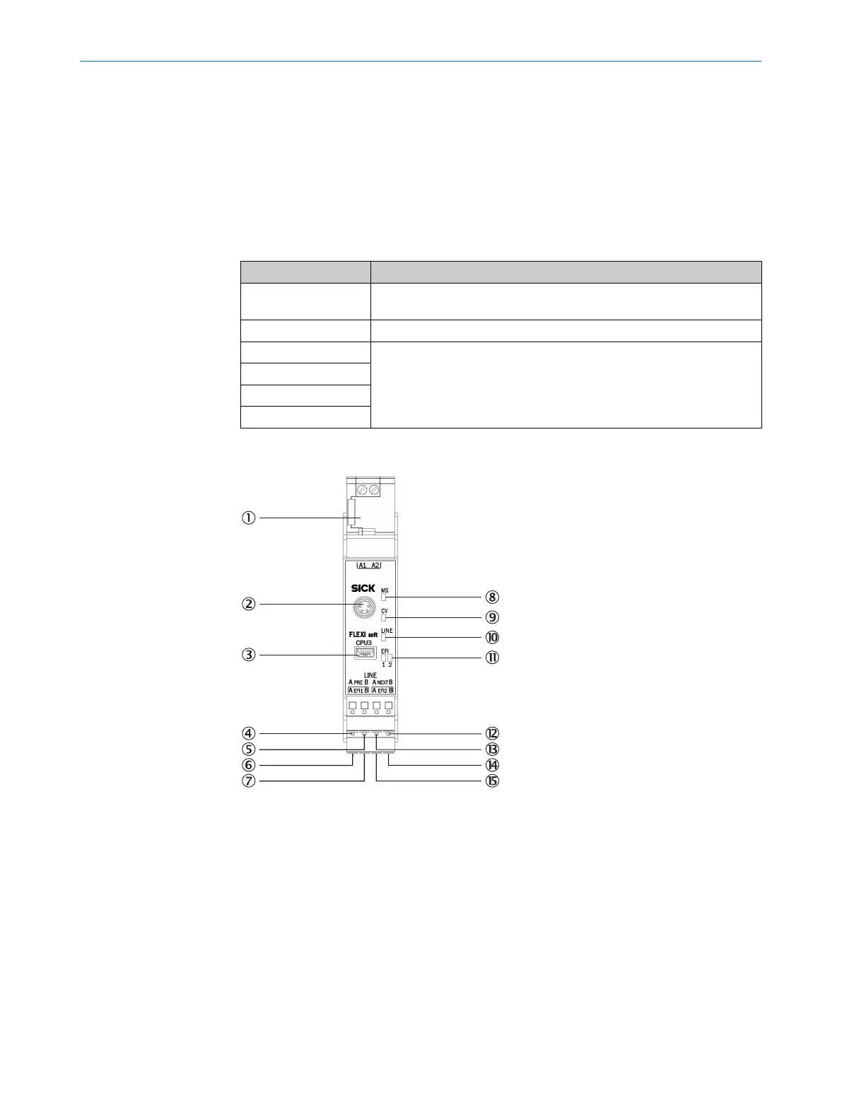
5.2.3 FX3-CPU3 main module
Figure 30: FX3-CPU3 main module
1
FX3-MPL1 system plug
2
RS-232 interface
3
USB interface
4
Line_PRE_A (previous)
5
Line_PRE_B (previous)
6
EFI1_A
7
EFI1_B
8
MS LED (Module St
atus)
9
CV LED (Configuration Verified)
ß
LINE LED
à
EFI1 and EFI2 LEDs
á
Line_NEXT_B (next)
ELECTRICAL INSTALLATION 5
8012478/1IG6/2023-02-24 | SICK O P E R A T I N G I N S T R U C T I O N S | Flexi Soft Modular Safety Controller
55
Subject to change without notice