â
Line_NEXT_A (next)
ã
EFI2_B
ä
EFI2_A
Table 20: Pin assignment on the FX3-CPU3 main module with FX3-MLP1 system plug
Terminal Pin assignment
A1 24 V power supply for all modules, with the exception of the supply to
t
he outputs (Q1 … Q4)
A2 Power supply GND
EFI1_A Connections for EFI or for Flexi Link
EFI1_B
EFI2_B
EFI2_A
Line_PRE_A Connections for Flexi Line
Line_PRE_B
Line_NEXT_A
Line_NEXT_B
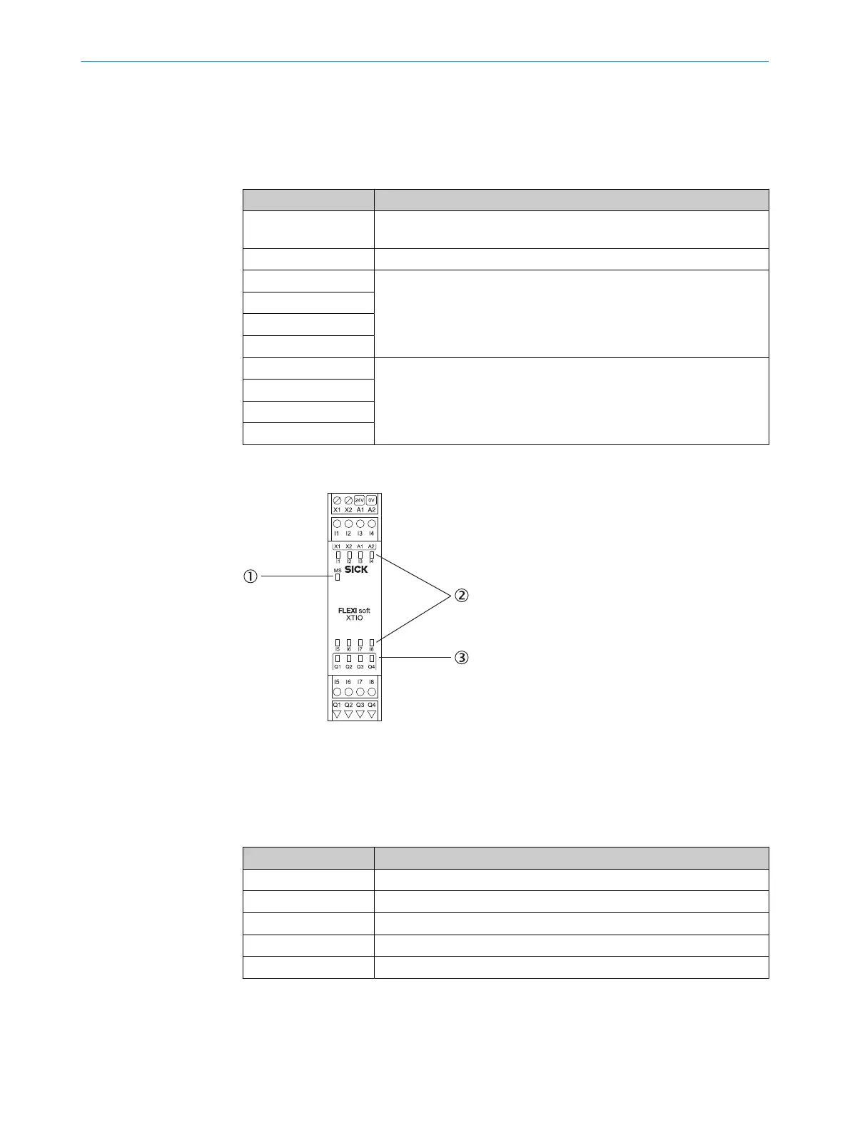
5.2.4 FX3-XTIO I/O module
Figure 31: FX3-XTIO I/O module
1
MS LED (Module Status)
2
8 input LEDs
3
4 output LEDs
Table 21: Pin assignment for the FX3-XTIO I/O module
Terminal Pin assignment
A1 24 V
A2 GND
I1 … I8 Safety inputs 1 to 8
Q1 … Q4 Safety outputs 1 to 4
X1/X2 Test output 1/Test output 2
5 ELECTRICAL INSTALLATION
56
O P E R A T I N G I N S T R U C T I O N S | Flexi Soft Modular Safety Controller 8012478/1IG6/2023-02-24 | SICK
Subject to change without notice