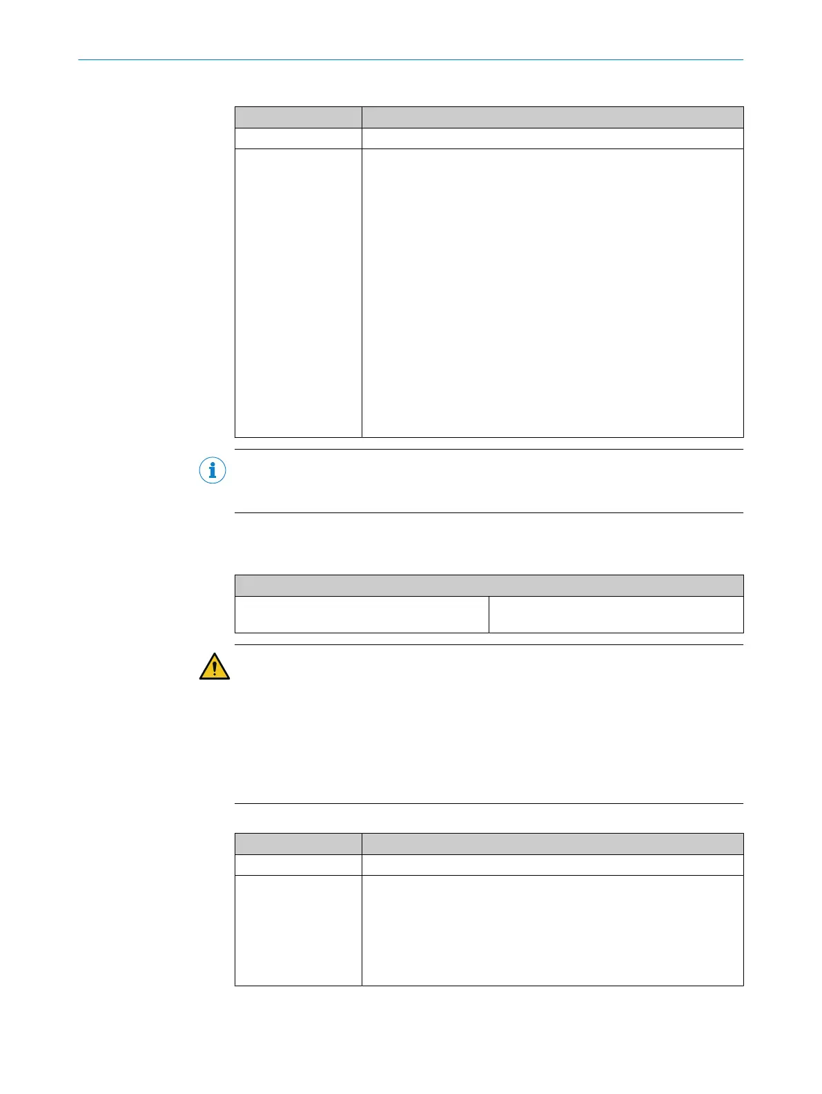
Table 73: Functions with testable type 2 safety single-beam sensors
Function Notes
Tested Possible
Series connec‐
t
ion/cascading
Wx12/24/27, Vx18:
•
Maximum 2 pairs per input can be cascaded with test pulse width =
4ms (standard element in the configuration software)
•
Maximum 5 pairs per input can be cascaded with test pulse width =
12ms (user-defined element required in configuration software)
L21:
•
Maximum 10 pairs per input can be cascaded with test pulse width
= 4ms (standard element in the configuration software)
•
Maximum 25 pairs per input can be cascaded with test pulse width
= 8ms (user-defined element required in configuration software)
L27/L28:
•
Maximum 7 pairs per input can be cascaded with test pulse width =
4ms (standard element in the configuration software)
•
Maximum 18 pairs per input can be cascaded with test pulse width
= 12ms (user-defined element required in configuration software)
►
Observe max. conductor resistance of 100Ω.
NOTE
F
or more information, please refer to the operating instructions for the testable type 2
safety single-beam sensors.
5.4.3.2 Testable type 4 safety single-beam sensors
Table 74: Connection of testable type 4 safety single-beam sensors
Electrical connection: example with FX3-XTIO
L41 Test input TI (sender) at X1
Output Q (receiver) at I1
WARNING
Impairment of fault detection due to cross-circuit
The dangerous state may not be stopped or not be stopped in a timely manner in the
event of non-compliance.
►
Prevent cross-circuits between the connection from the test output of the Flexi
Soft module to the test input of the sender and the connection from the output of
the receiver to the safe input of the Flexi Soft module with protected or separate
cabling.
Table 75: Functions with testable type 4 safety single-beam sensors
Function Notes
Tested Necessary
Series connec‐
t
ion/cascading
L41:
•
Maximum 10 pairs per input can be cascaded with test pulse width
= 4ms (standard element in the configuration software)
•
Maximum 25 pairs per input can be cascaded with test pulse width
= 8ms (user-defined element required in configuration software)
Note the maximum conductor resistance of 100 Ω.
5 ELECTRICAL INSTALLATION
86
O P E R A T I N G I N S T R U C T I O N S | Flexi Soft Modular Safety Controller 8012478/1IG6/2023-02-24 | SICK
Subject to change without notice