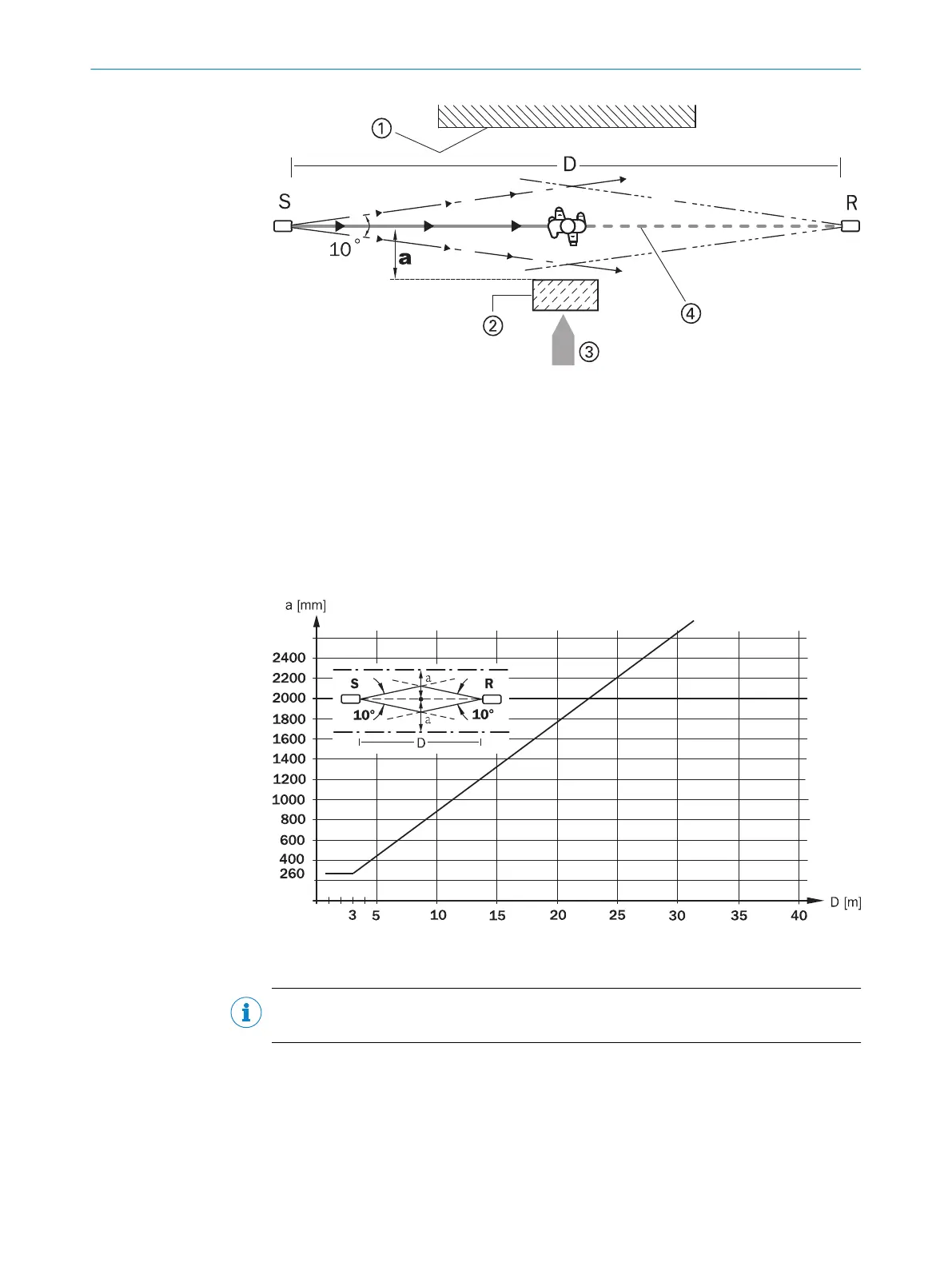
Figure 51: Minimum distance a to reflective surfaces, correct mounting and alignment
S: Sender
R: Receiver
D: Distance between sender and receiver
a: Minimum distance to reflective surface
1: L
imit to hazardous area
2: R
eflective surface
3: Ent
ry direction to hazardous area
4: Op
tical axis
Figure 52: Minimum distance a as a function of distance D for testable safety single-beam
sensor
s with aperture angle 10° (e.g. Wx12/24/27, Vx18)
NOTE
Eac
h set of operating instructions contains the diagrams for L21, L27/L28and L41.
5 ELECTRICAL INSTALLATION
88
O P E R A T I N G I N S T R U C T I O N S | Flexi Soft Modular Safety Controller 8012478/1IG6/2023-02-24 | SICK
Subject to change without notice