A 15-pin Micro D-Sub male connector is positioned on the front of the FX3-MOCx for
connec
ting up to two encoders.
Important information
NOTICE
T
he screws of the Micro-D-Sub male connector are to be tightened alternately by one
turn until a torque of 0.2Nm is achieved.
NOTE
•
T
o make installation easier, we recommend using the connecting cables and
encoder/motor feedback connection boxes that are available as accessories (see
"Accessories for the safety controller", page 182).
•
The signals are assigned based on the type of encoder used (see "Connection of
encoders", page 92).
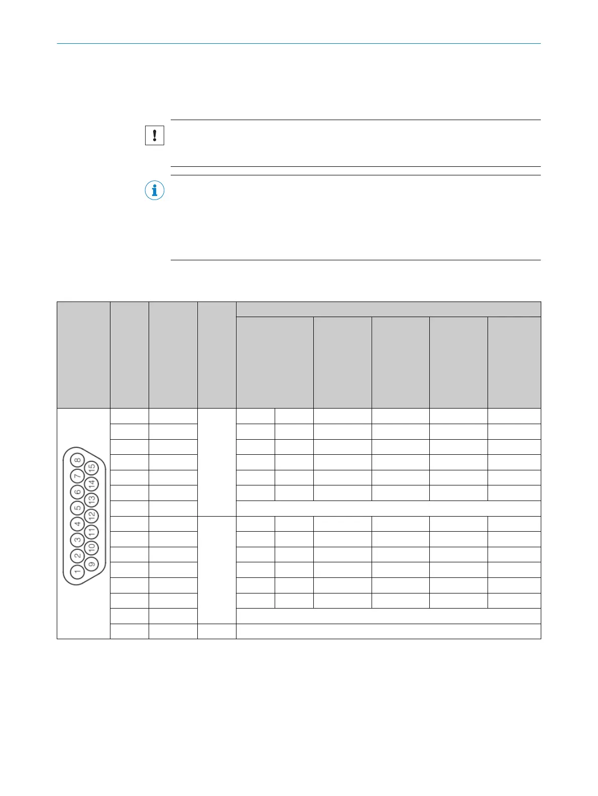
Pin assignment
Table 25: Pin assignment of the Micro-D-Sub male connector of the FX3-MOCx
Male con‐
nec
tor
Pin Signal
name
Encoder Wiring
1)
Sine/Cosine
encoder
A/B incre‐
mental
encoder, 2
pairs of out‐
puts
(HTL24V,
HTL12V,
TTL)
A/B incre‐
mental
encoder, 2
outputs
(HTL24V,
HTL12V,
TTL)
A/B incre‐
mental
encoder, 2
pairs of out‐
puts
(RS-422)
SSI
encoder
2)
1 ENC1_A+
1
Cos+ Cos A+ A A+ Data+
9 ENC1_A– Cos– Cos_Ref A– GND A– Data–
2 ENC1_B+ Sin+ Sin B+ B – –
10 ENC1_B– Sin– Sin_Ref B– GND – –
3 ENC1_C+ – – – – B+ Clock+
11 ENC1_C– – – – – B– Clock -
4 ENC1_24V 24V voltage supply for encoder 1
8 ENC2_A+
2
Cos+ Cos A+ A – Data+
15 ENC2_A– Cos– Cos_Ref A– GND – Data–
7 ENC2_B+ Sin+ Sin B+ B – –
14 ENC2_B– Sin– Sin_Ref B– GND – –
6 ENC2_C+ – – – – – Clock+
13 ENC2_C– – – – – – Clock -
5 ENC2_24V 24V voltage supply for encoder 2
12 ENC_0V 1 & 2 GND connection for encoder 1 and 2
1)
A combination of different encoder types is possible.
2)
Consider possible measures for common cause errors. See "Mo
tion Control FX3-MOC0", page 34 or "Motion Control FX3-MOC1", page 36.
5 ELE
CTRICAL INSTALLATION
60
O P E R A T I N G I N S T R U C T I O N S | Flexi Soft Modular Safety Controller 8012478/1IG6/2023-02-24 | SICK
Subject to change without notice