3
Tube bundle cable 1
4
Tube bundle cable 2 (option)
5
Pressure reducer unit
6
Instrument air as zero gas/test gas (option)
7
Test gas inlet
8
Sample gas outlet
9
Sample gas outlet on cell
ß
Fixing of line sample gas outlet on the cell
Connect instrument air
Connect instrument air to the pressure control unit.
ATTENTION
Risk of contamination of the analyzer by unclean instrument air.
b
Only use instrument air corresponding to the mandatory specification (see "Techni‐
cal data", page 78).
b
Install a suitable instrument air conditioning when necessary.
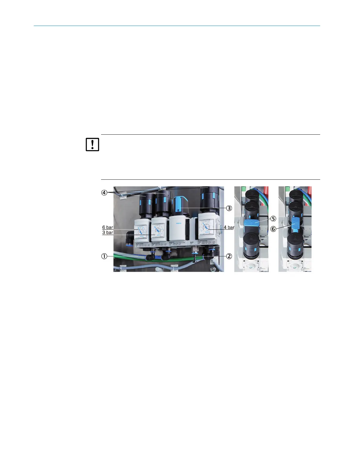
Figure 18: Pressure reducer unit
1
Instrument air inlet with zero gas quality
2
Instrument air inlet for induction air ejector only
3
Manual valve for instrument air selection
4
3 pressure reducers (adjustable)
5
Manual valve - closed position
6
Manual valve - open position
The instrument air is used as both induction air for the ejector (cell) and zero/control
air.
Instrument air can be connected in 2 ways:
b
One common instrument air supply for ejector air and zero/control air (inlet 1).
b
Separate instrument air supply for:
°
Ejector air (inlet 2)
°
and zero/control air (inlet 1)
Instrument air quality
The requirements for instrument air quality are lower when the air is only used as
ejector air than when used as zero/control air (zero gas quality) (see "Supply
gases", page 87).
b
When connected just as instrument air supply with zero gas quality to be used as
common air for both ejector air and zero/control air (on inlet 1):
INSTALLATION
2
8017585/YXD9/V3-1/2017-05 | SICK T E C H N I C A L I N F O R M A T I O N | MARSIC300
21
Subject to change without notice
 Loading...


